IR Controlled Car with Servo Motors | Embedded C Programming - Part 32
Published
Hi there! In this tutorial, we will blow off the dust from the SMARS car, which we actively used in the PIC10F200 tutorials series (Bluetooth Controlled Robot, Line Following Car, Obstacle Avoidance Robot). Here we will use this car without any changes, which means it is still driven by the hacked servo motors whose shaft can revolve freely. You can use the ready-to-go servos with 360-degree rotation, but they are more expensive and less widespread, and hacking regular motors is relatively easy. This tutorial also describes it in depth: “How to make a 360-degree Continuous Rotation Servo Motor?” so it’s up to you what to choose.
Unlike the tutorials mentioned above, we will control the car with an IR remote this time. You can use almost any remote which supports the NEC protocol. I doubt if a smartTV or air conditioner still uses this protocol but any simple remote from an Arduino kit (Figure 1) or light control (Figure 2) will work well.

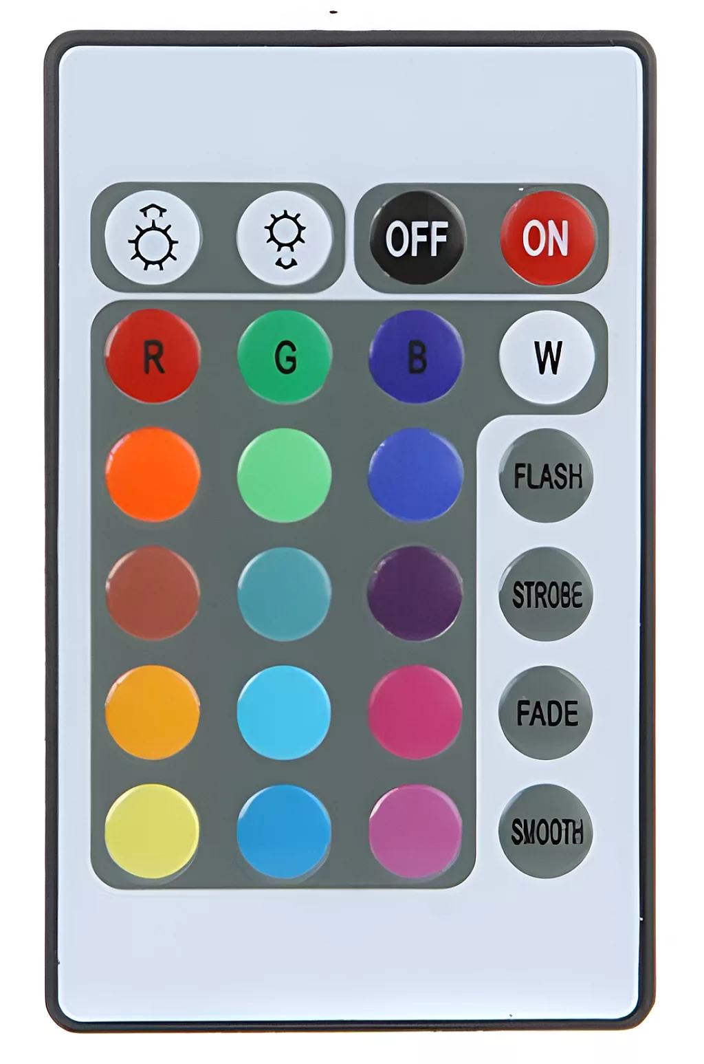
Also, you can test available remotes to see if any of them produces the required signal. I’ll talk about this in detail later. And we also dealt with the IR remotes in the PIC10F200 series (Infrared RGB LED controller) if you’d like to review those.
So, to refresh your memory, you can refer to these tutorials. If you missed the PIC10F200 series, I will repeat a lot of the required information here, so it isn’t necessary to go and review those, though it would certainly be helpful.
Servo Motors
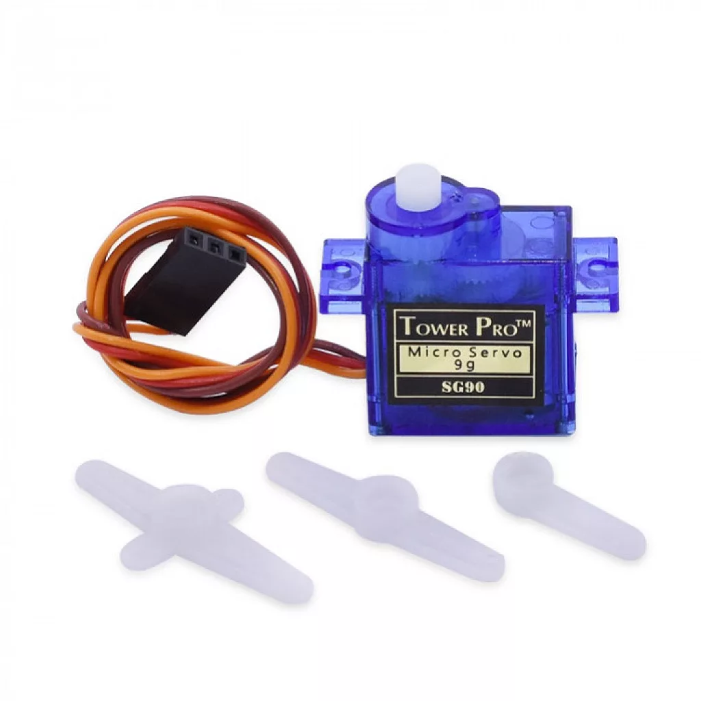
The appearance of the SG90 servo is shown in figure 3. As you can see, it consists of the servo itself and 3 changeable attachments, which can be attached to the servo’s shaft and fixed with a screw.
The servo has 3 wires; usually, they are orange, red, and brown. They mean the following - red and brown wires for the power supply (plus 5V and ground, respectively), while the orange wire is the control.
Control of the servo motor position is performed by means of the PWM. In the SG90 datasheet, you can find the following picture (Figure 4).
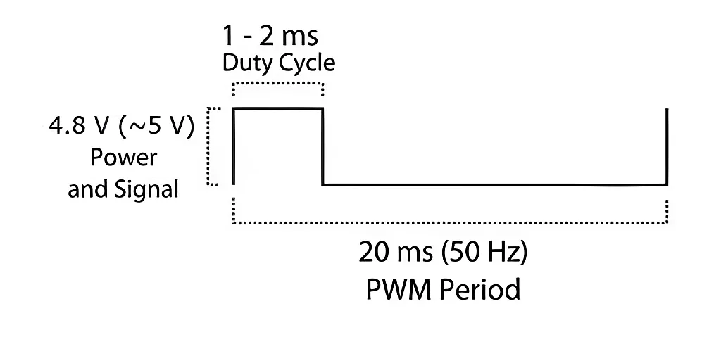
The position of the servo’s shaft is set by changing the pulse duration between 1 and 2 milliseconds, where 1 ms corresponds to the very far left position and 2 ms corresponds to the very far right position. Thus, 1.5 ms will put the shaft in the middle position. For 360-degree rotating servos, the 1.5 ms pulse corresponds to the stall position of the shaft, the pulse in the range of 1..1.5 ms will rotate the shaft in one direction, and the pulse in the range of 1.5…2 ms will rotate the shaft in another direction. The more the deviation of the pulse width from 1.5 ms, the higher is the rotation speed.
In Figure 4, you can see that the PWM period is 50 Hz, but from my experience, it’s the minimum period, so you can just set the stall time as 20 ms regardless of the pulse duration, meaning your actual period could be anywhere from 21 milliseconds to 22 milliseconds. Also, you don’t need to always send the pulse; you can send them just when you want to rotate the shaft to the given position and then disable the PWM.
However! You should know that in this case, the servo’s shaft will be released, and someone can rotate it manually relatively easily. But if you keep sending the pulses, the torque will still be applied to the shaft, and you will more likely break the gear rather than move it manually. So it depends on your task and requirements whether you should continuously send the modulated signal or just send it and then disable the PWM.
Car Chassis
The last thing you will need is the chassis, where you will assemble all the parts. If you are lucky enough to have a 3D printer, I recommend making this cool robot called SMARS. It was designed to be used with DC motors, but you can find the chassis and wheels version for the SG90 servos here and print it instead of the original one. All other parts can be taken from the original design.
The fully assembled robot is shown in Figure 5.
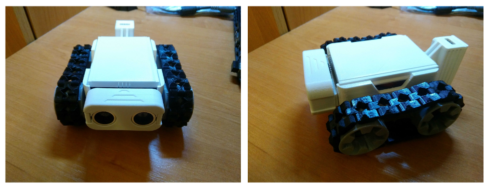
The “head” and the “tail” are not needed for this but they make the car look prettier.
If you don’t have a 3D printer, you can buy a ready-made chassis on eBay or AliExpress (search “Arduino car chassis”), or even cut it by yourself of plywood, acrylic, or textolite.
Infrared NEC Protocol
There are plenty of IR protocols, many of which are very different: they use different coding schemes, timings, and packet formats. We will consider one of the earliest and the most widespread protocols which was designed by NEC, and thus it’s called “NEC protocol”.
The packet consists of the preamble followed by 4 data bytes: address, inverted address, command, and data command (see Figure 6).

If you keep the button pressed for some time, only the first packet looks like the one shown in Figure 6. The other packets are shorter and follow with a period of 110 ms (see Figure 7).
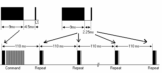
The bits are coded by the length of the pause (1.6ms for ‘1’ and 0.56ms for ‘0’) between pulses of the fixed length (0.56ms), see Figure 8.

On a physical level, the IR signal represents the modulated infrared beam emitted by the IR diode. The carrying frequency for the NEC protocol is 38 kHz. So the remote modulates the pulses with this frequency and sends it off. The IR receiver consists of the demodulator, which removes the carrying frequency and leaves just the initial pulses (Figure 9).
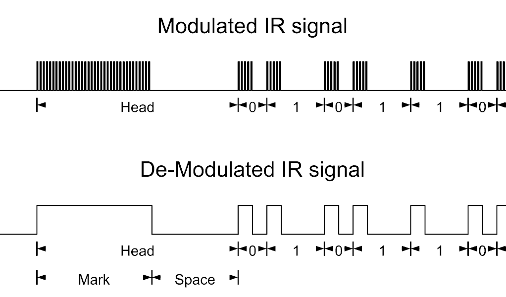
This modulation-demodulation process is used to increase the noise immunity of the IR channel, as there are a lot of the IR sources around us, and they all can cause false pulses.
IR Receiver
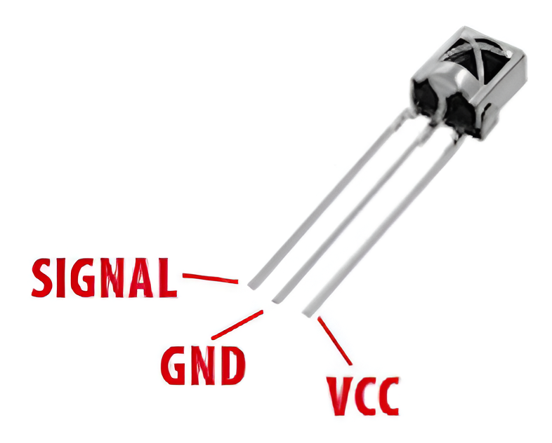
I recommend using the TL1838 (VS1838) IR receiver (Figure 10). It’s prevalent, cheap, and easy to use. As you see in Figure 10, it has just 3 pins: VCC, GND, and SIGNAL. The supply voltage is 2.7 - 6.0 V. This receiver has the in-built IR decoder, which means that there are ready-to-use pulses on the SIGNAL pin, so all we need to do is to directly connect this pin to one of the GPIOs of the microcontroller and measure the duration of the pulses to decode the IR packet.
RA and RB port change interrupt
Now that we have all the required information about the hardware we will use in this tutorial, let’s briefly consider the new module we will use- RA and RB port change interrupt.
We are already familiar with one type of the external interrupt - INTx, where x is the interrupt number from 0 to 2. We used these interrupts in the PID controller tutorial. Today we will familiarize ourselves with another type.
Each INTx interrupt has its own flag and is masked individually, while RA and RB port change interrupt has one flag for all pins. So if any of the allowed pins of port RA or RB changes its state, the interrupt (if unmasked) will be triggered. Also for INTx interrupt we could select the edge at which it will be triggered, and RA and RB port change interrupt is triggered at both high-to-low and low-to-high edges, and you can’t configure it to be specific.
These interrupts don’t belong to the peripherals, so to enable them you only need to enable the GIE bit, and don’t need to enable the PEIE bit (this is separate from the individual interrupts masking bits).
Let’s consider the registers which configure the RA and RB port change interrupt:
INTCON register which we already learned about in tutorial 8 and tutorial 20:
- bit #3 - RABIE (RA and RB Port change interrupt enable). Setting this bit to 1 enables the RA and RB Port Change interrupt, resetting this bit to 0 disables the RA and RB Port Change interrupt.
bit #0 - RAB0IF (RA and RB Port change Interrupt Flag bit). This bit is set to 1 by hardware. If it’s set to 1 then the RA and RB Port Change interrupt has occurred, if it’s 0 then no interrupt occurred. When set, this bit should be cleared by software.
INTCON2 register which we also already learned about in tutorial 4 and tutorial 20:
- bit #0 - RABIP (RA and RB Port change interrupt priority). If this bit is 0 then this interrupt has low priority, and if it is 1 then the interrupt has high priority.
IOCA and IOCB registers allow the specific pins to generate the RA and RB Port Change interrupt. If some bit of these registers is 1 then the corresponding pin can be the source of the interrupt, and if a bit is 0 then changes of the pin state won’t trigger the interrupt.
IOCA register has the following bits:
- bit #5 - IOCA5 (PORTA RA5 pin).
- bit #4 - IOCA4 (PORTA RA4 pin).
- bit #3 - IOCA3 (PORTA RA3 pin).
- bit #1 - IOCA1 (PORTA RA1 pin).
- bit #0 - IOCA0 (PORTA RA0 pin).
IOCB register has the following bits:
- bit #7 - IOCB7 (PORTB RB7 pin).
- bit #6 - IOCB6 (PORTB RB6 pin).
- bit #5 - IOCB5 (PORTB RB5 pin).
- bit #4 - IOCB4 (PORTB RB4 pin).
And that’s everything we need to know about these interrupts. You just need to remember that even if you configure the interrupts, you still need to configure your pin as an input to make it work properly.
Schematic Diagram
We’re done with the theoretical part, now we can switch to the schematic diagram of the device which is shown in Figure 11.
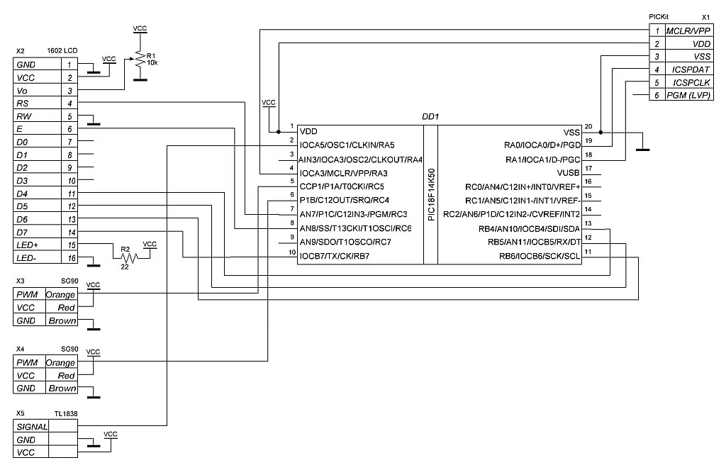
This time the schematic diagram is quite complex, but some familiar components still exist. The “heart” of the device is still the PIC18F14K50 MCU to which the PICkit programmer (X1), 1602 character LCD (X2), two servo motors (X3 and X4), and the IR receiver TL1838 (X5) are connected. The LCD is the same as we used in the previous tutorials, and its connection is also the same. Actually, the LCD is not needed for the working car, and we will remove it in the final installation. Its purpose is only to show the codes of the commands which are received via IR from the remote. If you already know these codes from some other source (for example, from here), you do not need to use the LCD, and you can skip its part in the program code. Otherwise, welcome onboard!
Two SG90 servos (X3 and X4) are connected to pins RC4 and RC5 of the MCU. This connection is not random as these pins are merged with the PWM outputs of the ECCP (enhanced capture-compare-PWM) module P1A and P1B.
The TL1838 IR receiver is connected to the RA5 pin of the MCU. We will use the pin change interrupt to capture the time of the pulses , which any pin of the RA and RB ports can trigger. As you can see in Figure 11, there are few options: only RA5 or RA4 pins of these ports are free. Besides, the RA4 pin starts as the analog pin and requires more configuration (one more line of code, but still…), so we better use the RA5 pin.
Maybe you remember that I mentioned that I use the 3.3V version of the LCD and power the device from the PICkit programmer with the VCC = 3.25V. The servos require a voltage of 4.5 - 6V, so in working conditions, we need to remove the LCD to prevent its damage (again, only if you use the 3.3V version as I do. If you have the 5V version, it’s fine to leave it).
That’s everything about the device schematic diagram so we can proceed to the next step.
Program Code Description
Let’s create a new project now. I’ve called it “IR_Car” but you can give it any name you want. Then create the new “main.c” file in it, as we are used to.
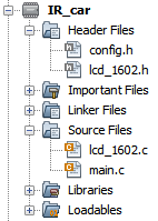
As in previous tutorials (for instance, tutorial 21), we will use the separate “config.h” file in which the configuration bits are defined. Also, we will need to copy and paste the “lcd_1602.h” and “lcd_1602.c”. One can take them from tutorial 22 or any later one. After all this, your project should look like Figure 12.
If you compare the schematic diagrams (Figure 12) in the current tutorial and Tutorial 22 (or later), you will notice that the connection of the display is equal, so if you took the LCD-related files from them, you don’t need to make any changes to them. And if you copied them from one of the previous tutorials, please remember to change the pin assignment; otherwise, your display won’t work properly.
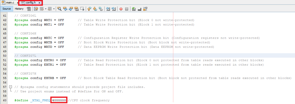
Before we start with the code of the program, let’s open the “config.h” file and make one change in it: in line 60, we need to replace the _XTAL_FREQ value with 4000000 instead of 32000000 (Figure 13). I will explain later why we need to do this.
Now let’s open the “main.c” file and write the following code.
#include <xc.h>
#include "config.h"
#include "lcd_1602.h"

#define PWM_VALUE   470     	//The value loaded into PWM register

volatile uint8_t pulse_count;   //Counter of the pulses received via IR
volatile uint16_t timestamp[70];//Timer1 values when the pulses are received
uint8_t ir_data[4];         	//4 bytes received via IR
uint8_t long_packet_valid;  	//Indicates that the long packet received via IR is valid
uint8_t short_packet_valid; 	//Indicates that the short packet received via IR is valid
uint8_t timer2_ticks;       	//Number of Timer2 ticks, required for producing the servo control signals
volatile uint8_t movement_allow;//Allows the movement of the car
volatile uint8_t timer1_ticks;  //Number of ticks of Timer1, needed to stop the movement when no packets are received via IR

void ca5_isr_handler (void) 	//Handler of the RA5 pin change interrupt
{
    timestamp[pulse_count] = (TMR1H << 8) + TMR1L;  //Read the Timer1 value into the current timestamp element
    pulse_count ++;                 	//Increment the number of received pulses
    volatile uint8_t dummy = PORTA; 	//Read the values of ports A and B
    dummy = PORTB;                  	//to prevent triggering this interrupt again
}

void timer2_handler (void)  	//Handler of the Timer2 overflow interrupt
{
    PSTRCONbits.STRA = 0;   	//Disable PWM steering at pin P1A
    PSTRCONbits.STRB = 0;   	//Disable PWM steering at pin P1B
    timer2_ticks ++;        	//Increment the timer2_ticks variable
    if (timer2_ticks == 7)  	//If timer2_ticks is 7 (30 ms x 7 = 210 ms)
    {
        if (movement_allow) 	//If movement is allowed
        {
            switch (ir_data[2]) //Check the command byte received via IR
           {
                case 64: CCP1CONbits.CCP1M = 0x0D; break; //Forward (P1A - active high, P1B - active low)
                case 9:  CCP1CONbits.CCP1M = 0x0C; break; //Right (P1A and P1B active high)
                case 7:  CCP1CONbits.CCP1M = 0x0F; break; //Left (P1A and P1B active low)
                case 25: CCP1CONbits.CCP1M = 0x0E; break; //Backward (P1A - active low, P1B - active high)
            }
            PSTRCONbits.STRA = 1;//Enable PWM steering at pin P1A
            PSTRCONbits.STRB = 1;//Enable PWM steering at pin P1B
        }
        timer2_ticks = 0;   	//Reset the timer2_ticks counter
    }
}

void timer1_handler (void)  	//Handler of the Timer1 overflow interrupt
{
    timer1_ticks ++;        	//Increment the timer1_ticks variable
    if (timer1_ticks >= 3)  	//If timer1_ticks greater or equal to 3
        movement_allow = 0; 	//then disable the car movement
}

void __interrupt() INTERRUPT_InterruptManager (void)    //Interrupt subroutine
{
    if((INTCONbits.RABIE == 1) && (INTCONbits.RABIF == 1))  //If pin change interrupt is enabled and pin change interrupt flag is set
    {
        if(IOCAbits.IOCA5 == 1)    	//If pin RA5 change interrupt is enabled
        {
            ca5_isr_handler();                  	//then invoke the ca5_isr_handler function
        }
        INTCONbits.RABIF = 0;      	// Clear global Interrupt-On-Change flag
    }
    if(INTCONbits.PEIE == 1)              	//If peripheral interrupts are enabled
    {
        if((PIE1bits.TMR2IE == 1) && (PIR1bits.TMR2IF == 1)) //If Timer2 interrupt is enabled and Timer2 interrupt flag is set
        {
            PIR1bits.TMR2IF = 0;                        	//Clear the Timer2 interrupt flag
            timer2_handler();              	//and invoke the timer2_handler function
        }
        else if((PIE1bits.TMR1IE == 1) && (PIR1bits.TMR1IF == 1))//If Timer1 interrupt is enabled and Timer1 interrupt flag is set
        {
            PIR1bits.TMR1IF = 0;                        	//Clear the Timer1 interrupt flag
            timer1_handler();             	//and invoke the timer1_handler function
        }
    }
}

void parse_code (void)          	//Function to parse the code received via IR
{
    short_packet_valid = 0;     	//Reset the short_packet_valid flag
    long_packet_valid = 0;      	//Reset the long_packet_valid flag
    for (uint8_t i = 0; i < pulse_count - 1; i ++)//In this loop we calculate the duration of the pulses
    {
        timestamp[i] = timestamp[i + 1] - timestamp[i];//by subtracting the neighbor values of the timestamp array
        if ((int16_t)timestamp[i] < 0)      	//If the obtained value is negative (which means Timer1 overflow)
            timestamp[i] += 65536;          	//then we add 65536 to the result
    }
    if ((timestamp[0] > 8500) && (timestamp[0] < 9500)) //Check if the first pulse is about 9 ms (9000 us)
    {
        if ((timestamp[1] > 2000) && (timestamp[1] < 2500)) //If the pause after the first pulse is about 2.25 ms
            short_packet_valid = 1;         	//then it's the short packet
        else if ((timestamp[1] > 4000) && (timestamp[1] < 5000)) //If the pause after the first pulse is about 4.5 ms
        {                                   	//then it's the start of the long packet
            for (uint8_t i = 0; i < 4; i ++)	//Clear all four elements
                ir_data[i] = 0;             	//of the ir_data array
            for (uint8_t i = 0; i < 32; i ++)   //We expect to receive 4 bytes which is 32 bits
            {
                if ((timestamp[i * 2 + 2] > 400) && (timestamp[i * 2 + 2] < 700)) //If the pulse is about 560 us
                {
                    if ((timestamp[i * 2 + 3] > 400) && (timestamp[i * 2 + 3] < 700)) //If the pause is also about 560 us (which corresponds to 0)
                    {
                        ir_data[i / 8] >>= 1;   //then we just shift the current ir_data element to the right
                    }
                    else if ((timestamp[i * 2 + 3] > 1400) && (timestamp[i * 2 + 3] < 1900))//If the pause is about 1700 us (which corresponds to 1)
                    {
                        ir_data[i / 8] >>= 1;   //then we shift the current ir_data element to the right
                        ir_data[i / 8] |= 0x80; //and add 1 to the MSB of it
                    }
                    else return;            	//If the pause is wrong then we leave the function immediately
                }
                else return;                	//If the pulse is wrong then we leave the function immediately
            }
            if (((ir_data[0] + ir_data[1]) == 255) && ((ir_data[2] + ir_data[3]) == 255))//If the first byte is the same as the negated second byte, and if the third byte is the same as the negated fourth byte
            {
                long_packet_valid = 1;      	//Then we set the long_packet_valid flag
                lcd_set_cursor (1, 1);      	//Set the cursor at the first position
                for (uint8_t i = 0; i < 4; i ++)
                {
                    lcd_write_number(ir_data[i], 0);//And write all four received bytes at the LCD
                    lcd_write_string(" ");
                }
            }
        }
    }
}

void main(void)
{
    //GPIO configure
    TRISAbits.RA5 = 1;  	//Configure RA5 pins as input (IR sensor input)
    IOCAbits.IOCA5 = 1; 	//Enable interrupt on RA5 pin
    TRISCbits.RC4 = 0;  	//Configure RC4 as output (first servo)
    TRISCbits.RC5 = 0;  	//Configure RC5 as output (second servo)

    //Oscillator module configuration
    OSCCONbits.IRCF = 5;	//Set CPU frequency as 4 MHz

    //Timer 0 configuration
    T1CONbits.RD16 = 1;  //Enable Timer1 register read/write in one operation
    T1CONbits.T1CKPS = 0;	//Prescaler 1:1
    T1CONbits.TMR1CS = 0;	//Internal instruction cycle clock
    T1CONbits.TMR1ON = 1;	//Timer1 is enabled

    //Timer 2 configuration
    T2CONbits.T2CKPS = 0b10;//Prescaler 1:16
    T2CONbits.TMR2ON = 1;   //Timer2 is enabled
    PR2 = 187;         	//Set the Timer2 period as 3 ms

    //ECCP module configuration
    CCP1CONbits.CCP1M = 0x0C;//PWM mode; P1A-P1D active high
    CCP1CONbits.P1M = 0;	//Single PWM output
    CCPR1L = PWM_VALUE >> 2;//Copy the upper 8 bits of the y into CCPR1L
    CCP1CONbits.DC1B = PWM_VALUE & 0x03;//Copy the lower 2 bits of the y into DC1B
    PSTRCONbits.STRSYNC = 1;//Output steering update occurs on the next PWM period

    //Interrupts configuration
    RCONbits.IPEN = 0;  	//Disable priority level on interrupts
    INTCONbits.RABIF = 0;   //Clear pin change interrupt flag
    INTCONbits.RABIE = 1;   //Enable pin change interrupt
    PIR1bits.TMR1IF = 0;	//Clear Timer1 overflow interrupt flag
    PIE1bits.TMR1IE = 1;	//Enable Timer1 overflow interrupt
    PIR1bits.TMR2IF = 0;	//Clear Timer2 overflow interrupt flag
    PIE1bits.TMR2IE = 1;	//Enable Timer2 overflow interrupt
    INTCONbits.GIE = 1; 	//Enable all unmasked interrupts
    INTCONbits.PEIE = 1;	//Enable peripheral interrupts

    lcd_init(0, 0); lcd_init(0, 0);   //Initialize the LCD without cursor and blinking (for some reason at the low frequency we need to do it twice)
    lcd_clear();        	//Clear the LCD
    lcd_write_string("Ready");//And type "Ready"

    pulse_count = 0;    	//Reset the pulse_count variable
    movement_allow = 0; 	//Reset the movement_allow flag

    while (1)           	//Main loop of the program
    {
        if (((((TMR1H << 8) + TMR1L) - timestamp[pulse_count-1]) > 16000) && (pulse_count > 2)) //If time after the last pulse is more than 16 ms and the number of received pulses is greater than 2
        {
            parse_code();   //Then we consider this as the end of the packet and parse it
            if (long_packet_valid || short_packet_valid)	//If we received the long or short packet
            {
                movement_allow = 1; 	//Then we set the movement_allow flag
                timer1_ticks = 0;   	//And reset the timer_ticks variable
            }
            for (uint8_t i = 0; i < 70; i ++) //In any case we clear the timestamp array
                timestamp[i] = 0;
            pulse_count = 0;        	//and clear the pulse_count variable
        }
    }
}
This program is one of the largest among all our tutorials, so this will compensate for the absence of the new modules in this tutorial.
In line 1, we, as usual, include the “xc.h” file to use the PIC MCU-related variables, functions, and macros. In line 2, we include the “config.h” file, in which the configuration bits are defined. And finally, in line 3, we include the “lcd1602.h” file, which consists of the 1602 LCD-related functions.
In line 5, we define the PWM_VALUE macro as 470. It represents the speed of the car’s movement, and its value will be described later.
In lines 7-14, there are the variables declarations:
- pulse_count (line 7) would be better to call “edge counter” as it counts the changes of the state of the IR sensor output. It counts both high-to-low and low-to-high transitions.
- timestamp (line 8) is the array in which the time the state changes of the IR sensor output is saved. To measure this time, we will use Timer1.
- ir_data (line 9) is the array in which the four bytes received via IR are stored (see Figure 6).
- long_packet_valid (line 10) is the flag that becomes 1 if all the timings of the received long packet are valid and the format of the received bytes also corresponds to the NEC protocol.
- short_packet_vlaid (line 11) is the flag that becomes 1 if the timings of the short (repeat) packet are valid (see Figure 7).
- timer2_ticks (line 12) is the counter of the Timer2 overflows. It’s required to produce the correct signal to control the servo motors (see Figure 4).
- movement_allow (line 13) is the flag that becomes 1 if the valid packet is received via IR and if the command is recognized (forward/backward/left/right).
- timer1_ticks (line 14) is the counter of the Timer1 overflows. It’s required to stop the car after a certain time after receiving the last command.
You may notice that some variables have the modifier volatile. It’s used for those variables which are used both in a main loop and in the interrupts handlers. If you don’t put this modifier, the compiler will consider this as two different variables - one in the main loop and another in the interrupt handlers. As such, they will have different values, breaking the program’s logic. So using the volatile modifier in such cases is always a good idea. But don’t overuse it because it takes more time for the CPU to process the volatile variable.
In lines 16-22, there is the function ca5_isr_handler which is the interrupt handler of the RA5 pin change.
In lines 24-45, there is the function timer2_handler which is the Timer2 overflow interrupt handler.
In lines 47-52, there is the function timer1_handler which is the Timer1 overflow interrupt handler.
In lines 54-77, there is the INTERRUPT_InterruptManager subroutine which we always use to process the interrupts.
We will consider the interrupt handlers and subroutines later after getting familiar with the program’s main function.
In lines 79-126, there is the parse_code function which parses the received packet. This is the most complex function of this program, and we will consider it later as well.
And finally, in lines 128-190, there is the main function. But before considering it, let’s first get familiar with the modules we will use in this program and their use.
As you already got from the former description, we will use Timer1 (described in tutorial 14) and Timer2 (described in tutorial 20) and the RA and RB Port change interrupt functionality. Besides, we will need the ECCP module in PWM mode (described in tutorial 20). And here, the limitations of the PIC18F14K50 MCU begin. With the PIC10F200, we had no such limitations because we didn’t have any peripheral modules except for the very restricted timer/counter. And here, we would want to use the hardware modules wherever possible because they usually work better than the software emulation.
The first limitation is that the PIC18F14K50 MCU has only one ECCP module. So if we use it in the PWM mode, we can’t use it in the capture mode to automatically save signal change time at the IR sensor output. So we need to decide which mode to choose. The width of the pulses from the IR remote is relatively long (starting from 560 us, see Figure 8), and we don’t need a very high accuracy, unlike the distance meter we made in tutorial 14. So we will use the RA and RB Port change interrupt to detect the signal changes and simply read the Timer1 counting register value at this moment.
Speaking of Timer1, we will configure it with the tick period of 1 us to simplify the comparison of the read result with Figure 8.
Timer2 will be used to work with the ECCP module in PWM mode. And here we face another limitation. Even though the ECCP module can produce up to 4 PWM signals, they are either all the same or half are inverted compared to another half. To normally run the car, we need to produce the pulses with a width of 1-2 ms and a period of greater than 20 ms. And here, we get the third limitation. To get the period of 20 ms with the 8-bit timer, its clocking frequency should be 256 / 20 ms = 12.8 kHz. Even if we use the 1:16 prescaler (and as you remember, the postscaler isn’t applicable in the PWM mode because these bits are used to increase the PWM resolution up to 10 bits), the CPU frequency should be not higher than 12.8 x 16 = 204.8 kHz. OK, we can run the MCU at such a low frequency, but in this case, it will not be able to process the IR signal promptly and will miss some pulses.
It was a challenge for me to make it work with such limitations. But finally, I found the solution. To generate a signal similar to the one shown in Figure 4, we don’t need to have a period of 20 ms; moreover, we can’t get it to work with such conditions because we need two PWM signals, one of which can be either the same as the second one, or the same as the inverted second one. So I decided to set the PWM period to 3 ms. In this case, if I set the PWM pulse width as 50%, it will give the pulses of 1.5 ms at both PWM outputs, whether or not they are mutually inverted. Now, if I set the pulse width at about 60%, the pulse width will be 1.8 ms, and the inverted pulse width will be 3 - 1.8 = 1.2 ms. The deviation from the average value of 1.5 ms for the first motor will be 1.8 - 1.5 = 0.3 ms, and 1.2 - 1.5 = -0.3 ms for the second motor. This makes the motors spin in different directions but at the same speed, which is exactly what we need! But how do we obtain the period of 20+ ms like in Figure 4? Well, that’s quite simple! We enable the PWM outputs not all the time but during one Timer2 period of seven. So the full generated period will be 3 ms x 7 = 21 ms, which suits us. And the pulse width will be less than 2 ms because the pulse will be output only during the first Timer2 period of seven, and during the other six periods, the output signal on both pins will be 0.
It’s probably unclear now, but I hope it will become more apparent after considering the program code, so let’s return to it.
The configuration part of the main function occupies lines 130-173. First, we configure the required IO pins (lines 131-134). Pin RA5, connected to the IR sensor output, is configured as input without a pull-up resistor (line 131), as TL1838 has the push-pull output. Also, we allow pin RA5 to generate the RA and RB Port change interrupt (line 132) by setting the corresponding bit of the IOCA register.
Then we configure pins RC4 and RC5 as outputs (lines 133 and 134, respectively). These pins are connected to the control inputs of the servo motors (see Figure 11) and will be driven by the ECCP module.
Next, we set the CPU frequency as 4 MHz (line 137). This is the compromise value. On one hand, this is the maximum frequency at which we can get the 3ms period of Timer2; on another, it’s the minimal frequency at which the IR signal is processed without any misses and delays.
In lines 140-143, we configure Timer1:
- Enable reading/writing of the timer counting register in one operation (line 140), as we will need to read this value manually and quite often.
- Set the timer prescaler as 1:1 (line 141) because at the CPU frequency of 4 MHz, the timer clocking frequency is 4 MHz / 4 = 1 MHz, giving the timer’s tick duration of 1 us - the value we need.
- Set the internal source Fclk/4 as the timer’s clocking source (line 142).
- Enable the timer (line 143).
In lines 146-148, we configure Timer2:
- Set the timer’s prescaler as 1:16 (line 146). This gives the timer’s clocking frequency 4 MHz / 4 / 16 = 62.5 kHz. This gives the timer’s tick duration of 1 / 62.5 kHz = 16 us. So to get the timer period of 3 ms, we need 3000 / 16 = 187.5 pulses. Let’s round this value to 188 pulses. To set this period, we need to write the value 187 into the PR2 register, which we do in line 148.
- In line 147, we enable the timer.
In lines 151-155, we configure the ECCP module:
- We set the PWM mode with P1A-P1D pins active high (line 151). Actually, this value will be changed every time we receive a new command to move the car, as in different cases, we need different combinations of the active level of the pins P1A and P1B.
- Configure the PWM mode as the option with the single output (line 152). Technically, we can still have up to 4 outputs in this mode but they are enabled separately using the output steering feature.
- Set the PWM pulse duration (lines 153 and 154). Here we use the macro definition PWM_VALUE which is equal to 470. Let’s calculate the duration of this pulse in ms. So we set the Timer2 period as 148 ticks. This is the 8-bit value. But for the PWM, this period is artificially extended to 10 bits, giving the value of 188 x 4 = 752 pulses. The PWM duty cycle is 470 / 752 = 0.625, and the pulse duration is 0.625 x 3 = 1.875 ms, which makes the servo motor spin fast in one direction. This pulse duration is applicable if the active level of the pin is high. Otherwise, the pulse duration will be 3 - 1.875 = 1.125 ms, which makes the servo spin with the same speed but in the other direction.
- In line 155, there is the option that I have selected empirically. It makes the output steering changes applied only on the next period of Timer2. Without setting it, the changes are applied immediately which can produce a very short (several microseconds) pulse, which nevertheless totally messes up the servo control. So setting this option is vital for our application.
In lines 158-166, we configure the interrupts. Most of the lines in this part we already have met in previous tutorials:
- In line 158, we disable the interrupt priorities. As we don’t need a very high accuracy, it won’t hurt if timer interrupt is processed in the competing conditions before the pin change interrupt and vice versa.
- In line 159, we clear the RA and RB port change interrupt flag, and in line 160, we unmask the corresponding interrupt.
- In line 161, we clear the Timer1 overflow interrupt flag; in line 162, we unmask the corresponding interrupt.
- In line 163, we clear the Timer2 overflow interrupt flag; in line 164, we unmask the corresponding interrupt.
- In line 165, we enable all unmasked interrupts; in line 166, we enable the peripheral interrupts.
In line 168, we initialize the LCD. For some reason, at low CPU frequencies, we need to call the lcd_init function twice; otherwise, it doesn’t work in 4-bit mode and displays a total mess.
In line 169, we clear the LCD and then write “Ready” (line 170) to indicate that the device is ready to receive commands from the IR remote.
In lines 172 and 173, we clear the pulse_count and movement_allow variables, respectively. And here, the initialization part is over.
The program’s main loop occupies lines 175-189 and is relatively short.
First, we check if the difference between the current Timer1 value and the current timestamp element is greater than 16000 and if the pulse_count is greater than 2. The timestamp value is obtained in the RA and RB port change interrupt handler as the current Timer1 value. But if there are no pulses, then the timestamp will not be updated anymore because the interrupt will not be triggered. That’s why we make this check in the program’s main loop. So if 16000 us (or 16 ms) has passed since the last pulse, we don’t expect any more pulses in this packet, and it’s completed and can be processed. The second condition about pulse_count > 2 is needed because if the number of pulses is less than 2, the packet can’t be complete.
So if these two conditions are met, we proceed to the packet processing. First, we invoke the parse_code function (line 179), inside which we check if the full or repeat packet has been received and if this packet is valid.
If one of the packet types is valid (line 180), we set the movement_allow flag to enable the moving of the car (line 182) and reset the timer1_ticks variable (line 183), which, as I already mentioned, is used to stop the car after some time after the last packet received.
Finally, regardless of the packet’s validity, we clear the timestamp array (lines 185-186) and reset the pulse_count variable (line 187).
That’s everything about the main function of the program. Now, let’s consider the interrupt processing and start with the interrupt subroutine INTERRUPT_InterruptManager (lines 54-77).
Previously we processed all interrupts inside this function, but this time I decided to make a dedicated handler function for each interrupt to make the code more readable, as we’re going to process three interrupts.
The interrupt subroutine doesn’t differ much from the ones we used in the previous tutorials. At least the concept is the same: check if the interrupt is unmasked then check if the interrupt flag has been raised, make something useful, and clear the interrupt flag.
According to the above algorithm, we first check if the RA and RB Port change interrupt is unmasked (RABIE = 1) and if the corresponding flag RABIF is set (line 56). Then we check if the interrupt from the RA5 pin is allowed (line 58). If all these conditions are met, we invoke the ca5_isr_handler function (line 60) and clear the RABIF flag.
Then, in line 64, we check if the peripheral interrupts are enabled (PEIE = 1). As I mentioned before, the RA and RB Port change interrupt is not a peripheral one, so we don’t need to do this check for it, but for timer interrupts, we must.
So if peripheral interrupts are enabled, we check if the Timer2 overflow interrupt is unmasked (TMR2IE = 1), and if the corresponding flag TMR2IF is set (line 66), then we clear this flag (line 68) and invoke the timer2_handler function (line 69).
In lines 71-75, we do the same for Timer1.
Now let’s consider the interrupt handler functions; some are quite interesting.
In lines 16-22, the RA and RB port change interrupt handler ca5_isr_handler. It is invoked when the signal from the IR sensor changes. When this happens, we need to save the Timer1 value to calculate the pulses’ duration and decode the IR code. We do this in line 18, where we copy the value of the Timer1 counter register TMR1 into the element of the timestamp array with the index pulse_count (line 18). Then we increase the pulse_count value to save the next value in the next array element (line 19). Lines 20 and 21 are tricky. I mean, this is another unclear thing done in the PIC18F14K50 MCU. So if we just do the regular routine, such as doing something useful and then clearing the interrupt flag, then the RA and RB port change interrupt will be triggered again and again as if the flag is still set. Previously, I didn’t find the solution of this phenomena and used the INTx interrupts but this time I decided to beat it finally. In the data sheet of this MCU I found a small note (Figure 14).

So, as you see, we need to read the PORTA and PORTB registers to fix this, which we do in lines 20 and 21. As we don’t need these registers’ values, we just copy them into the dummy variable. I declared it with the volatile modifier to prevent its optimization by the compiler, as it also sees that even though we assign the variable, we still do nothing with it.
The timer2_handler (lines 24-45) is the function that controls the movement of the car in different directions, and there are also some tricks in it. I already explained the algorithm for controlling the car ,so let’s see how it’s implemented.
In lines 26 and 27, we disable the steering of the PWM signal at pins P1A and P1B, respectively. By doing this, we keep the P1A (RC5), and P1B (RC4) pins low regardless of the PWM duty cycle. Then we increment the timer2_ticks variable (line 28). In line 29, we check if the value of this variable reaches 7. This is what I talked about earlier. Six Timer2 periods (which, as you remember, are 3 ms), we keep both RC4 and RC5 pins low. And during the seventh period, we can send the pulses to these pins if the remote receives the right command.
So we check if the movement_allow variable is set (line 31). We have already considered that this variable becomes 1 if we have received the full or repeat packet via IR. If so, we check what command we have received (line 33). We will return to the distinction and displaying of the commands later, and now we are at the point where we know the codes of the remote buttons from somewhere. In Figure 6, the IR packet consists of four bytes: address, inverted address, command, and inverted command. The first two bytes are the same for the remote, so we need to check only the command byte, which is stored in the second element of the ir_data array.
In our program, we will distinguish four commands: to move the car forward or backward, turn left or turn right. I have the remote shown in Figure 1, the most left one, and I will use the following buttons:
“+” - forward;
“-” - backward;
“⏭” - turn right;
“⏮” - turn left.
So the lines 35-38 may be different in your code depending on the remote and the car chassis you use.
If the command “forward” has been received (line 35) we need to configure the RC4 and RC5 outputs in a way that makes the car move forward. The code of the “+” button in my remote is 64, your value may be different, and you can see it in the LCD.
To understand the expression CCP1CONbits.CCP1M = 0x0D we need to recall the PWM modes (Table 1 from Tutorial 20). I will repeat the information we are interested in here:
CCP1M3 | CCP1M2 | CCP1M1 | CCP1M0 | Mode |
1 | 1 | 0 | 0 | PWM mode: P1A, P1C active high; P1B, P1D active high |
1 | 1 | 0 | 1 | PWM mode: P1A, P1C active high; P1B, P1D active low |
1 | 1 | 1 | 0 | PWM mode: P1A, P1C active low; P1B, P1D active high |
1 | 1 | 1 | 1 | PWM mode: P1A, P1C active low; P1B, P1D active low |
As you can see, the CCP1Mx bits set the active level of pins P1A-P1D. If we configure a pin as active high, then during the PWM_VALUE time, it will be high, and during the rest of the Timer2 period, it will be low, producing a pulse of 1.875 ms, as I explained earlier. If we configure it as active low, then its behavior will be vice versa: during the PWM_VALUE time, the pin will stay low, and then for the rest of the period, it will be high, and in this case, the pulse duration will be 1.125 ms.
Now, let’s look at the table and line 35 again—the expression CCP1CONbits.CCP1M = 0x0D means that we configure the P1A and P1B pins in the following way: “PWM mode: P1A, P1C active high; P1B, P1D active low”. So at pin P1A (RC5), we will have the long pulses (as it is active high), and at pin P1B (RC4), we will have short pulses (as it is active low), which will make servos spinning with the same speed but in the opposite directions. In my chassis, the motors are mounted so that their shafts should spin in the opposite direction to make the wheels spin in the same direction, which may be different in your setup.
The other lines (36-38) do the same but set the different PWM modes when the corresponding command has been received. When the “Right” command has come (line 36), which in my case has the code 9, then we configure P1A and P1B pins as follows: “PWM mode: P1A, P1C active high; P1B, P1D active high,” which will produce the identical long pulses at both PWM outputs and make the wheels spin in a different direction which turns the car to the right.
When the “Left” command is received (line 37), which has the code 7, then we configure P1A and P1B pins as follows: “PWM mode: P1A, P1C active low; P1B, P1D active low” which will produce the short pulses at both PWM outputs and make the wheels spin in an opposite direction to the “Right” command.
And finally, when the “Backward” command is received (line 38), code 25, then P1A and P1B are configured as “PWM mode: P1A, P1C active low; P1B, P1D active high” which will produce the pulses opposite the “Forward” command, and the car will move backward.
After configuration of the PWM mode we enable the output steering at both P1A and P1B pins (lines 40, 41). This enabling will become active only at the next period of Timer2 (remember line 155 of the configuration?), and in such a way we can eliminate the short pulses that might appear if the changes are applied immediately.
Finally, we reset the timer2_ticks variable to start the whole algorithm from the very beginning (line 43).
So, let’s summarize this all. During the six periods of Timer2 (which gives 3 x 6 = 18 ms) both pins RC4 and RC5 remain low. If there is no valid packet received via IR during the seventh period they remain low leaving the servos alone and adding another 3 ms to the whole servo period. If we receive a valid command then during the seventh period of Timer2 either long (1.875 ms) or short (1.125 ms) pulse will be produced at pins RC4 and RC5 depending on the command code, after that the RC4 and RC5 pins will become low for another six Timer2 periods and so on and so forth.
If we receive the repeated packet, the last command will be repeated while we keep the button on the remote pressed. But how to stop the car now? We need to reset the movement_allow variable after we stop receiving the repeat packets from a remote.
And we do this in the Timer1 overflow interrupt handler timer1_handler (lines 47-52). This function is the most boring in this program. In line 49, we increment the timer1_ticks variable. As you remember, this variable is reset when a valid IR packet is received (line 183). Then, in line 50, we check if it is greater or equal than 3. If this happens, this means that since the last valid packet has passed 65536 us x 3 = 196 608 us or about 200 ms. So in 200 ms after the last received packet the car is stopped by resetting the movement_allow variable (line 51).
And finally, let’s consider the longest function of this program - parse_code (lines 79-126). It is invoked from the main function in 16 ms after the last activity on the RA5 pin (lines 177-179) and inside it we check if the received packet is valid, and what the type of the packet is.
First, we reset both packet validation flags: short_packet_valid (line 81) and long_packet_valid (line 82).
Next, we need to calculate the duration of the pulses and pauses. It’s quite simple to do this by subtracting the previous timestamp element from the current one. So this difference will give the time interval between the signal changes in microseconds (that’s why we configured Timer1 so that its tick takes 1 us). The result will be saved into the same array timestamp not to create new instances and save the RAM. So keep in mind that this array plays two roles: during receiving the packet it consists of the Timer1 values at the moments when the signal from IR changes; and after the parse_code function it consists of the durations of the pulses and pauses between them.
So, in line 83 we start the new loop from 0 to pulse_count -1. It ends with pulse_count - 1 instead of just pulse_count because for obvious reasons the number of pulses is less than the number of signal changes by 1. Inside this loop we subtract the value of the current timestamp element from the next one and save the result in the current element (line 85). It may happen that the current timestamp value was taken at the end of the current Timer1 period, and the next value was taken at the next Timer1 period. In this case the duration will be negative. We check this case in line 86. Please pay attention that we need to cast the type of the timestamp to the int16_t in order to compare it with 0 because the default type of it is uint16_t, and is always positive, so the condition would always be false without the type casting. So if this happens, we just add the Timer1 period (which is 65536) to the timestamp value, and then the result will be correct.
Now, as we have calculated all the pulses and pauses durations we can start checking the packet validity.
First, we check the first pulse. According to Figure 7, it should be 9 ms, or 9000 us. But IR sensors can have a deviation of the pulse width, also the signal edges can be smooth enough which also adds some error, and moreover, the frequency of the MCU is not stable as well, so there are a lot of sources of distortion of the pulse and pause durations. That’s why we check not the exact value of 9000 us but the range of ±5%…±10% from this value. In our case we check if the pulse width is greater than 8500 us and smaller than 9500 us (line 89). If this condition is met, we check the pause width. There can be three situations (Figure 7):
- the pause is 2.25 ms which means the repeat packet;
- the pause is 4.5 ms which means the beginning of the full packet;
- the pause is different which means fault packet.
So first we check if the pause is in the range of 2…2.5 ms (line 91). If this is true then it’s the valid repeat packet, so we can set the flag short_packet_valid (line 92) and end the function.
Then we check if the pause is in the range of 4…5 ms (line 93). If it is true then it’s the beginning of the full packet, and we need to decode it according to Figure 7 and 8.
We clear all four elements of the ir_data array (lines 95, 96). Then we start the loop from 0 to 32 (line 93) to receive all 32 bits (or 4 bytes) of the packet according to Figure 6. Inside the loop we first check if the pulse width is in the range of 400…700 us (average value is 560 us according to Figure 8) (line 99). If the pulse width is valid we check the pause width. If it is in the same range (line 101) then this is the 0 bit (Figure 8), and we just shift the current ir_data element at one bit to the right (line 103). The shift direction is to the right because data is sent LSB first (Figure 6).
Then we check if the pause width is in the range of 1400…1900 us (average value is 1690 us) (line 105). If it is so, then we shift the current ir_data element at one bit to the right (line 107) and add 1 at the MSB of it (line 108).
If the pause width or pulse width are invalid then we immediately leave the function (lines 110, 112) leaving both short_packet_valid and long_packet_valid flags low.
I think I should now explain a bit more about the array indexes used in this loop. Timestamp has either index 2 * i + 2 for pulse or 2 * i + 3 for pause. Each bit is coded by one pulse and one pause, thus to transmit 32 bits we need 32 * 2 = 64 timestamp values, that’s why we multiply the i value by 2. As for the adding 2 or 3, this is also simple - the first pulse is the packet header (9 ms and 4.5 ms), so the first payload pulse has the index 2, and the first pause has the index 3.
ir_data array has the index i / 8. It’s also not difficult. The value of i represents the bits while ir_data elements are the bytes which, as you know, consist of 8 bits.
So, by line 113 we have already decoded the IR packet, and have the address, inverted address, command, and inverted command (Figure 6) in the ir_data array.
Finally, before stating that the packet is valid, we need to check if the first element of the array is the same as the inverted zero element, and if the third element is the same as the inverted second element. We do this in line 114. The simplest way to do this is to add the tested elements. If one of them is the same as the inverted other one, then their sum will be equal to 255, or 0xFF. Why is it so? In the inverted value all the 0 and 1 are swapped in comparison to the initial value. So when we sum them, each resulting bit will be either 1 + 0 or 0 + 1 which anyway gives 1. And all ones in the binary form are exactly 255 in decimal form or 0xFF in hexadecimal form.
So now line 114 should be clear. If this condition is met, we finally can set the long_packet_valid flag (line 116) indicating that we have received the valid packet. The next four lines are just for the information and are needed if you don’t know the codes of the buttons of the remote. We set the cursor at the first position (line 118) then write all four received bytes (line 120) separating them with the spaces (line 121).
And finally that’s everything about the program code. This is not the simplest program we had but we need to grow in our knowledge, so this is not surprising. Let’s now proceed to the testing of our device.
Testing of the IR-controlled car
Let’s assemble the device according to Figure 11, compile and build the project and flash it into the PIC18F14K50 MCU. If everything is assembled and programmed correctly, you should see the “Ready” text on your LCD (well, if you use it at all). I will consider that you, like me, have some remote and don’t know the codes of the buttons.
Point the remote at the IR sensor and press the button whose code you want to know. If the remote has the NEC encoding, and if you connected everything correctly, you should see something like this in your LCD (Figure 15).

Here I pressed the button “+” on the remote. As you see the address byte is 0, and the inverted address is 255 which is correct. The command byte is 64 and the inverted command code is 191. If we sum these two values, we will get 64 + 191 = 255, which is also correct. Let me now show you what’s going on at the IR sensor output when this command comes with my logic analyzer (Figure 16).

As you can see, the signal can be decoded even visually: the long pause is 1, and the short pause is 0. Please note that the TL1838 sensor has a low active level, so the pulse level is “0” and the pause level is “1”.
Now you can see that after the heading long pulse there is the following sequence of zeros and ones: 00000000111111110000001011111101. Let’s group them by 8 into bytes and convert them into decimal system: 00000000 11111111 00000010 11111101
00000000b = 0
11111111b = 255
00000010b = 64
11111101b = 191
These results match the values in Figure 15 which is not surprising.
Now let’s see the output PWM signal which corresponds to this button. As I said before, the “+” button stands for the “Forward” signal, at which one motor should spin in one direction, and another in the opposite direction. The logic analyzer shows the following (Figure 17).

As you can see, everything is as I described before. The period of the pulses is about 21 ms (7 x 3 ms), the width of the long pulse is 1.871 ms (theoretical value is 1.875 ms), and the short pulse is 1.123 ms (theoretical value is 1.125 ms). Short and long pulses are shifted because they both are generated within one Timer2 period of 3 ms.
The “Backward” command has the same waveform, just the pulses are swapped (Figure 18).

The signals corresponding to the “Right” and “Left” commands are shown in Figure 19 and 20, respectively.


As you can see, in the last two cases the signals at both outputs are the same.
When you send some of the movement commands to the car you should see that its wheels are spinning in the right direction. If the direction is wrong, correct lines 35-38 of the code. If the motors don’t spin at all and just crackle, most likely there is not enough voltage to overcome the initial torque. My PICkit 3 doesn’t provide much current to the device so I had to use the external power supply like battery or USB port. Again, I’m reminding you that if you use the 3.3V LCD, you need to disconnect it before applying 5V to the car to prevent its damage.
And that’s everything I wanted to tell you in this tutorial. We didn’t learn much in terms of new MCU modules but we have studied how to decode IR signals from the remote. Probably in one of the next tutorials I will show you the opposite process - how to generate the IR signal for controlling some external devices.
As homework I suggest you make a tweak of the car. For now, it has the following flaw. After you release the button which is recognized by the car, you can press any button on the remote, and the car will keep repeating the last command. Fix this issue, so the car reacts only on four buttons and ignores the others.

Get the latest tools and tutorials, fresh from the toaster.

