MIDI Controller Knobs & Buttons
Published
What would be the coolest project / product for you to work on? Just as how Josh answered in the Ask an Electrical Engineer - Jobs and Careers Edition | Part 2 video, yes I agree! The coolest project would be something that combines electronics and something that you enjoy. In my case, it’s music. That’s why in this project, I’m going to show you something that would be useful if you are a musician.
So what is this project about? This project is easy to understand and create but it’s very useful in recordings or even in live performances, a MIDI Controller. But before we discuss the details, let's first discuss what MIDI is.
What is MIDI?
MIDI stands for Musical Instrument Digital Interface. It is a protocol followed by different companies to connect different devices used in music production such as digital musical instruments, audio interfaces, controllers, computers, tablets, smartphones, etc. If you are a musician, a DJ, producer, or an artist, you’ll probably use MIDI in composing a song, performing live, or even just learning music.
History of MIDI
In the early 1980s, Ikutaro Kakehashi, founder of the Roland company, saw that there was no standardized method of interfacing digital musical instruments between different companies. So he suggested developing a standard to Tom Oberheim, founder of Oberheim Electronics. Representatives from different companies such as Roland, Yamaha, Korg, Kawai, and Sequential Circuits discussed it and came up with the MIDI standard.
How does MIDI operate?
MIDI operates by transmitting or receiving MIDI messages via MIDI ports. A MIDI message can be a channel message, a system exclusive message, a system common message, or a system real-time message. As you can see, there are four categories of MIDI messages but we will not discuss all of them here. We will just focus on channel messages since its concept is enough to understand how MIDI protocol and this MIDI Controller project work.
All categories of MIDI messages have at least one command byte and then may have zero, one, or more additional bytes. For channel messages, it has or requires two or three bytes. Channel messages are used to control hardware synthesizers, digital audio workstations (DAWs) or virtual studio technology (VST) instruments, etc. The message is composed of two or three bytes. The first byte in a channel message is divided into two nibbles (or two 4-bits). If you’re not familiar with binary and hexadecimal number systems, I suggest you check out this tutorial here: Binary, Hexadecimal, and Other Base Numbers. The first nibble of the first byte contains the name of the message. The message name could be note off, note on, polyphonic aftertouch, control change, program change, channel pressure (aftertouch), or pitch bend change.
| Message Name | Description |
| Note Off | Sent when a note is released. |
| Note On | Sent when a note is depressed. |
| Polyphonic Aftertouch | Sent when pressure is still being applied even after depressing a key. |
| Control Change | Sent when a controller value changes. |
| Program Change | Sent when the patch number changes. |
| Channel Pressure (Aftertouch) | Sent when pressure is still being applied even after depressing a key. However, its difference from Polyphonic Aftertouch is that this message can be used to send the single greatest pressure value (of all the currently depressed keys). |
| Pitch Bend Change | Sent when the pitch bender’s position is changed. |
The second nibble contains the MIDI channel number. The MIDI protocol has 16 channels so the second nibble has enough number of bits to specify the channel number.
| cccc | MIDI Channel Number |
| 0000 | 1 |
| 0001 | 2 |
| 0010 | 3 |
| 0011 | 4 |
| 0100 | 5 |
| 0101 | 6 |
| 0110 | 7 |
| 0111 | 8 |
| 1000 | 9 |
| 1001 | 10 |
| 1010 | 11 |
| 1011 | 12 |
| 1100 | 13 |
| 1101 | 14 |
| 1110 | 15 |
| 1111 | 16 |
The second and the third byte of the channel message depends on the name of the message. The table below is a summary of the MIDI channel messages.
| Message Name | Byte 1 | Byte 2 | Byte 3 |
| Note Off | 1000 cccc | This byte specifies the number of the key or note to release. | This byte specifies the velocity or how quickly the note is released. |
| Note On | 1001 cccc | This byte specifies the number of the key or note to turn on. | This byte specifies the velocity or how quickly or forcefully the note is depressed. |
| Polyphonic Aftertouch | 1010 cccc | This byte specifies the number of the key or note. | This byte specifies the pressure value. |
| Control Change | 1011 cccc | This byte specifies the controller number: [0 - 119] | This byte specifies the controller value: [0 - 127] |
| Program Change | 1100 cccc | This byte specifies the new program (patch) number. | N/A |
| Channel Pressure (Aftertouch) | 1101 cccc | This byte specifies the single greatest pressure value of all depressed keys. | N/A |
| Pitch Wheel Change (Pitch Bend) | 1110 cccc | This byte specifies the least significant 7-bits of pitch-bend value. | This byte specifies the most significant 7-bits of pitch-bend value. |
For example, you have a MIDI Keyboard Controller and you press the middle C note (which is C4 or has a decimal number of 60), what happens is that your keyboard sends 90 3C XX (in hexadecimal) to your synthesizer or VST instrument through its MIDI port. The synthesizer or VST instrument will then generate a middle C sound. Then when you release the key, the keyboard sends 80 3C 00 and the sound turns off.
Let’s try to analyze this. When we press a key on a keyboard, it sends a Note On channel message. As we can see on the data [90 3C XX], the first byte here is 90 (1001 0000 in binary). The first nibble, which represents the message name is 9 (hexadecimal) or 1001 (binary) and the second nibble, which represents the MIDI channel number is 0 (hexadecimal) or 0000 (binary). If you look at the table above, 1001 is Note On. So it makes sense that the keyboard sends 90 when a key is pressed. So the channel number here is 1 since the second nibble is 0000. The second byte in a Note On channel message specifies the number of the key or note to turn on. It’s 3C or 60 (decimal) in this example. If you search the number of the middle C note, you’ll find that its number is 60 in decimal. The third byte XX specifies the velocity value. It determines how soft or hard you pressed the key. I put XX because this depends on how you press the key, but the velocity value ranges from 0 to 7F (0 to 127 in decimal).
The second data sent after releasing the key is 80 3C 00. When a key is released on a keyboard, the keyboard sends a Note Off channel message which is just similar to Note On. So if you look at the table above again, Note Off is 1000 which makes sense why the first nibble of the first byte is 8. The channel number and the second byte is just the same in the first data. The third byte in a Note Off message, which also represents the velocity value is rarely used so by default we just set it to zero.
Another example is the sustain pedal. The sustain pedal uses a control change channel message. So for example we have a B0 40 7F data, it means that the sustain pedal is depressed. The first byte B0 shows that the message name is control change and the MIDI channel number is 1. The second byte represents the control function, which in this example is 40 (64 in decimal). The control function number 40 is assigned to the sustain pedal. The third byte represents the control function value which in a sustain pedal function is just either 00 (off) or 7F (on) if half-pedaling is not supported. Since the third byte is 7F, it means that the sustain pedal is on or depressed. To learn more about control change messages and its functions, check this page: MIDI 1.0 Control Change Messages (Data Bytes).
How do MIDI devices connect?
As mentioned earlier, MIDI messages are transmitted or received via the MIDI ports. Common MIDI ports used are the 5-pin DIN and USB. The 5-pin DIN MIDI port uses MIDI cables to connect MIDI devices. If you observe MIDI devices that use 5-pin DIN, you’ll notice that at least it has a MIDI IN and MIDI OUT ports and some even have MIDI THRU ports.

The MIDI IN port is where the MIDI device receives MIDI messages from another MIDI device while the MIDI OUT port is used by a MIDI device to transmit MIDI messages to another MIDI device. The MIDI THRU port is used to duplicate the data received by the MIDI IN port. This way, we can connect more devices if there’s ever a lot of MIDI devices that we want to connect.

Older MIDI devices use the 5-pin DIN port but as the USB protocol was discovered, most MIDI devices that I encounter today now use a USB port to send or receive MIDI messages. In this case, you will only need one cable [usually a printer cable for USB Type B port but other USB MIDI ports today use mini B, micro B, and even type C] instead of using two MIDI cables for the MIDI IN and OUT ports of a 5-pin DIN MIDI interface. But the disadvantage is that, since USB is a host controlled bus, you need a host to control all your MIDI devices. It’s either a computer, a smartphone, or a tablet. But this could be an advantage as well, because if you’re going to use a computer or a tablet, then setting up the MIDI devices will be much easier.
MIDI Devices
There are many MIDI devices that you can see today and each of them have different features. To avoid confusion, we can simply categorize them into four categories.
Synthesizers

Synthesizers are MIDI devices that generate sounds based on the MIDI messages it receives. They could be hardware synths in which the signal processing and the generation of sound is done by the internal circuitry or a software synth that you can easily use by running it on a computer, smartphone, or a tablet. Modern keyboard synthesizers are like a combination of software and hardware that has an internal dedicated computer with a keyboard and external controls.

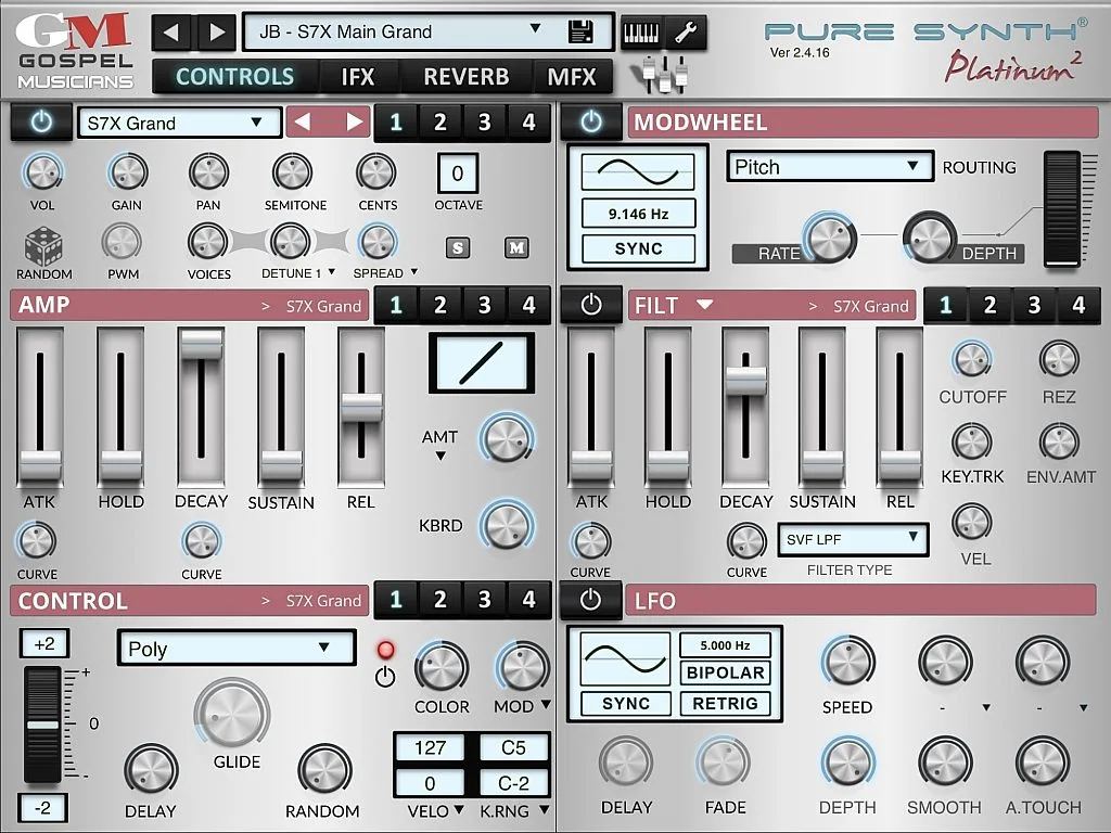
Some musicians nowadays prefer to use software synths because of the portability and the ability to edit sound parameters easily. With just a laptop or an iPad, you can load a lot of different sound libraries and use it for recording or live performances, though you still need to connect it to a MIDI keyboard. But at least you don’t need to purchase a lot of expensive and very heavy keyboard synthesizers.
Controllers
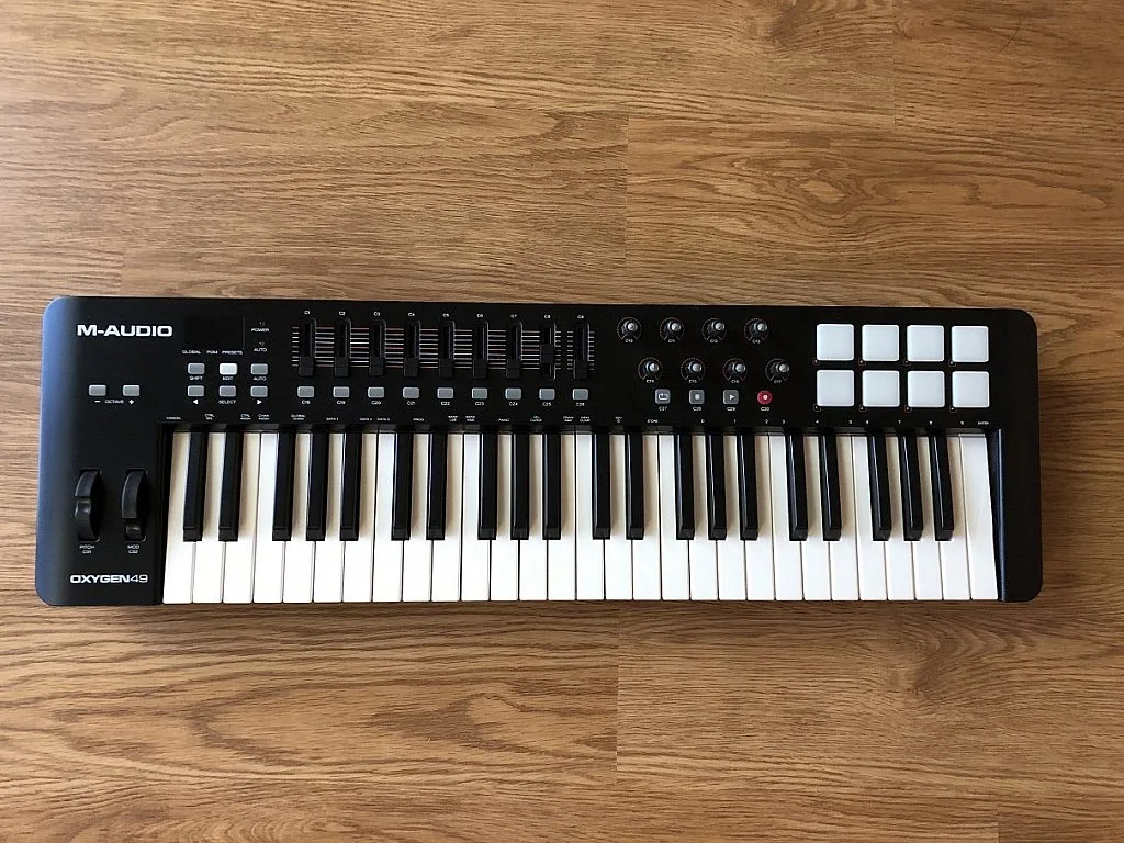
Another group of MIDI devices that musicians physically control are MIDI controllers. Examples are keyboard controllers, electronic drums, drum pads, knobs, buttons, faders, etc. MIDI controllers don’t generate sounds. What they generate are MIDI messages. So for MIDI controllers to become useful, they are paired with a hardware or a software synthesizer. If you see a keyboard synthesizer, it’s just basically like a synthesizer combined with a MIDI controller.
Sequencers
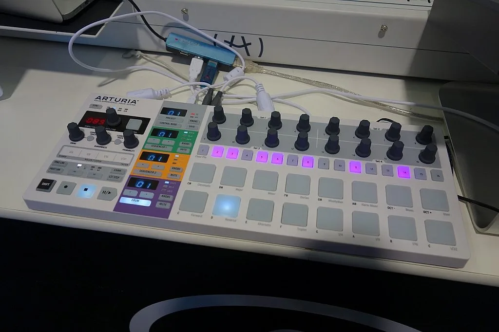
Sequencers are another group of MIDI devices used by musicians to record MIDI messages and then play it during live performances. It is a combination of MIDI software and hardware synthesizer. Most keyboard synthesizers have a built-in sequencer where you can record, edit, and play MIDI sequences during live performance. A MIDI sequencer is very useful especially if the band is not complete since it acts as an electronic version of a musician.
Networks
The last group of MIDI devices are the networks. Basically, MIDI networks provide connection between other MIDI devices. They can be used to route MIDI messages from one MIDI device to another device. A MIDI network could just be hardware or a combination of software and hardware.
What MIDI Isn’t
Just to avoid confusion, MIDI is just data. So you can’t transmit audio with MIDI. What you transmit or receive is data containing messages or instructions on how a synthesizer generates a sound, the notes to be played, the value of an effect parameter, etc.
What type of MIDI Controller is this project?
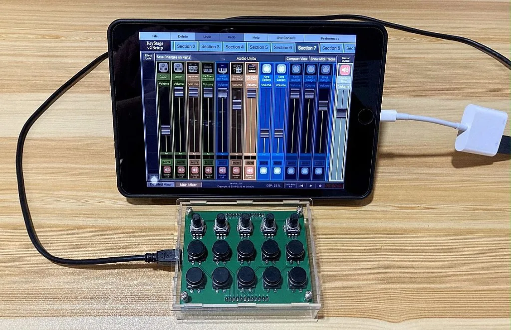
Now that we’ve already discussed MIDI, let’s proceed to the details of the project. So this project is a MIDI Controller that has knobs and buttons. Recently, I’ve been using software synths (iOS apps) a lot for live performances. For me, using an iPad or even an iPhone is more convenient and portable than carrying lots of heavy hardware keyboard synthesizers. The apps in iOS are also cheaper than buying keyboard synthesizers. They are even cheaper than the apps that you can purchase on macOS or Windows.
Using software synths through an iPad makes my life easier as a keyboardist. However, controlling the volume levels, or changing the value of the effects, or switching from one sound to another using the screen is not that ideal. That’s why I decided to create a simple MIDI Controller that has knobs for controlling volume levels or the value of an effect and buttons to mute or solo a sound, or switch from one sound to another sound. This MIDI Controller may not be perfectly designed but it’s something that I can easily create and program.
Schematic Diagram
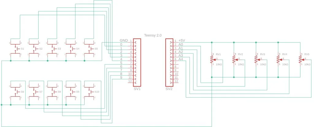
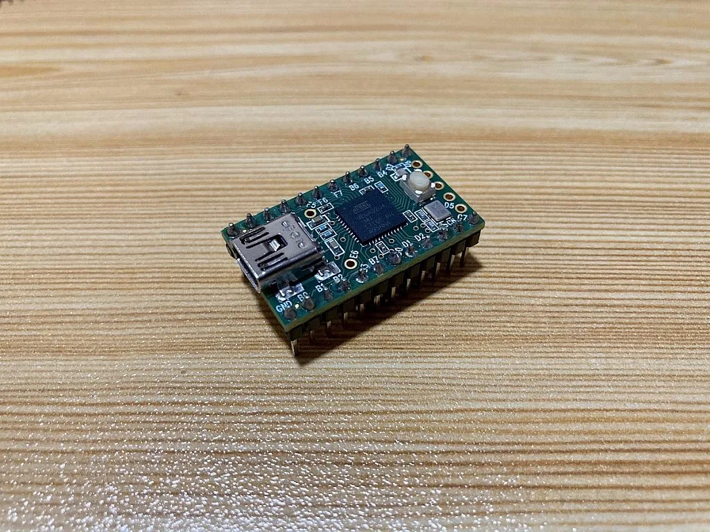
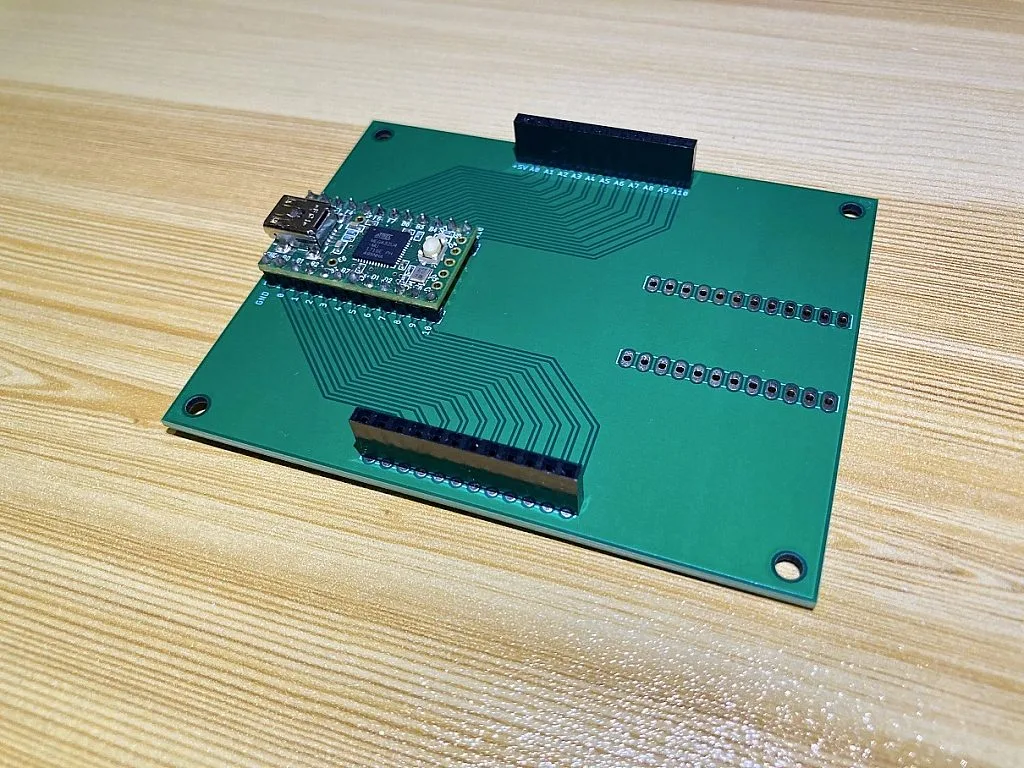
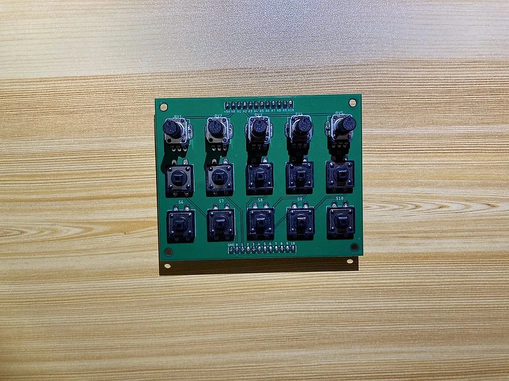
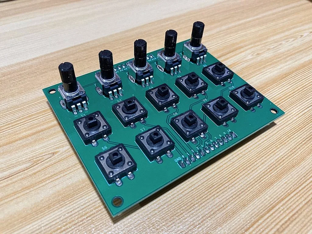
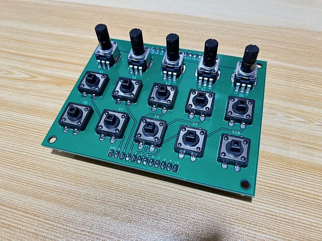
This is the schematic diagram of the MIDI controller and as you can see, there are 5 potentiometers and 10 pushbuttons used in this project. The potentiometers and pushbuttons are connected to a Teensy 2.0 board which acts as the MIDI device that sends MIDI messages to the host which could be a computer, a tablet, or a smartphone. There are other Teensy boards that are faster than the Teensy 2.0 which use an ATmega32U4 microcontroller. But during the time that I was looking for a Teensy board, the Teensy 2.0 was the only available board that I could purchase locally. So I just bought it because it’s still fast enough for simple applications like this. For cheaper options, you may like to use the Teensy LC or for faster applications, the Teensy 4.1 board.
The advantage of using Teensy boards is that they have a USB MIDI library that you can easily use in the Arduino IDE to program them as a MIDI device. So you can program them to send a MIDI message each time a pushbutton is pressed or the voltage across the wiper terminal of a potentiometer changes. As you can see in the schematic diagram, the pushbuttons are connected to the digital pins (0-9) of the Teensy 2.0 board. Whenever they are pressed the Teensy 2.0 sends a MIDI message to the host to toggle something on the software synth depending on how the pushbuttons are mapped to the software synth. For the potentiometers, they are connected to the ADC pins (A0-A4) of the Teensy 2.0. The Teensy 2.0 reads the voltage across the wiper terminal of the potentiometers and each time the voltage changes, it sends a MIDI message to the host which could be used to set the volume of a software synth or the value of its effects.
Parts
These are the parts I have used in this MIDI Controller:
1. Teensy 2.0
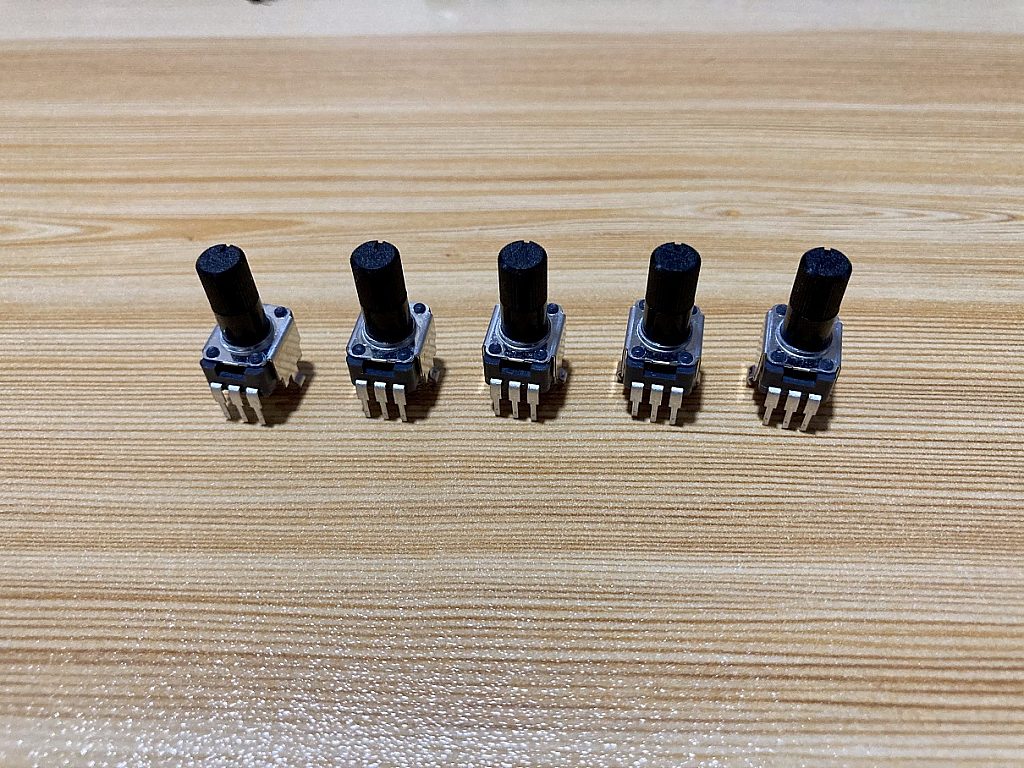
2. RK09K1130081 10kΩ Linear Potentiometer
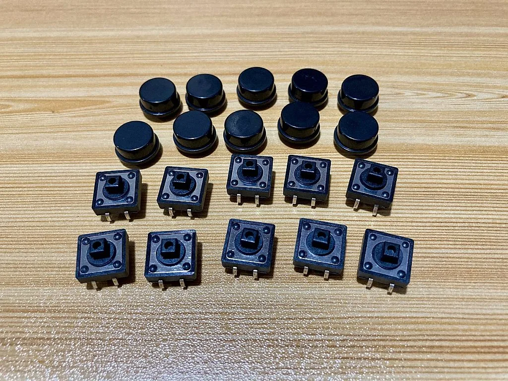
3. 12mm Tactile Switch with Cap
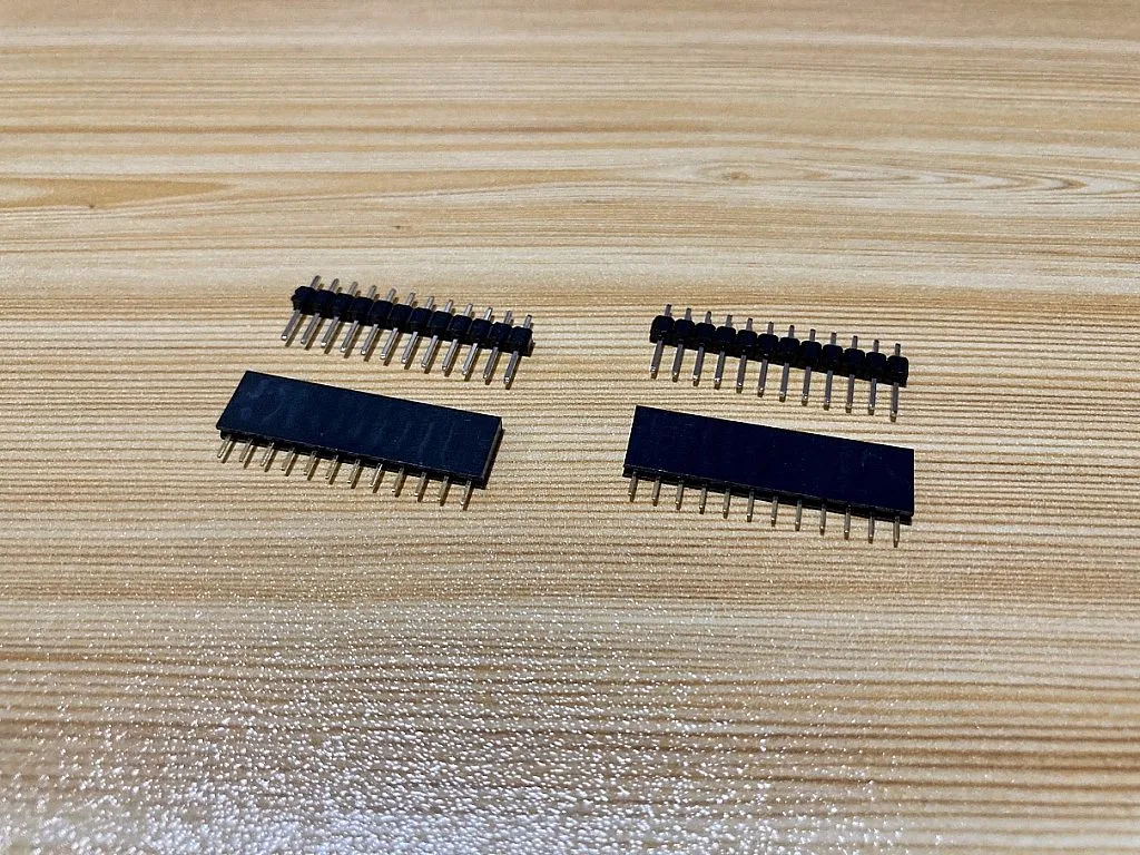
4. 12-pin Male and Female Headers
Software Setup
To program the Teensy 2.0 board, you will need to install the following:
1. Arduino IDE
Since we’re going to program the Teensy 2.0 using the Arduino IDE, you need to download the Arduino IDE from their website and install it. If you have already installed the Arduino IDE, just check the version that you have installed to verify it supports the next installer that we are going to install.
2. Teensyduino
After installing the Arduino IDE, the next thing you’re gonna need is the Teensyduino. The Arduino IDE doesn’t come with support for the Teensyduino, so you need to download the Teensyduino installer from their website and install it to integrate its files with the Arduino IDE. As of now, the latest Arduino IDE is version 1.8.13 and Teensyduino 1.53 supports this Arduino IDE version. For instructions on how to install Teensyduino, you can refer to the same webpage where you download the Teensyduino installer.
Code
/* USB MIDI Controller Knobs and Buttons
   You must select MIDI from the "Tools > USB Type" menu
   http://www.pjrc.com/teensy/td_midi.html
*/

#include <Bounce.h>

// the MIDI channel number to send messages
const unsigned char channel = 1;

// Create Bounce objects for each button.  The Bounce object
// automatically deals with contact chatter or "bounce", and
// it makes detecting changes very simple.
Bounce button0 = Bounce(0, 5);
Bounce button1 = Bounce(1, 5);  // 5 = 5 ms debounce time
Bounce button2 = Bounce(2, 5);  // which is appropriate for good
Bounce button3 = Bounce(3, 5);  // quality mechanical pushbuttons
Bounce button4 = Bounce(4, 5);
Bounce button5 = Bounce(5, 5);  // if a button is too "sensitive"
Bounce button6 = Bounce(6, 5);  // to rapid touch, you can
Bounce button7 = Bounce(7, 5);  // increase this time.
Bounce button8 = Bounce(8, 5);
Bounce button9 = Bounce(9, 5);

// MIDI CC number for button 0 to 9

const unsigned char button0_CC = 9;
const unsigned char button1_CC = 14;
const unsigned char button2_CC = 15;
const unsigned char button3_CC = 20;
const unsigned char button4_CC = 21;
const unsigned char button5_CC = 22;
const unsigned char button6_CC = 23;
const unsigned char button7_CC = 24;
const unsigned char button8_CC = 25;
const unsigned char button9_CC = 26;

unsigned char b0 = 0;
unsigned char b1 = 0;
unsigned char b2 = 0;
unsigned char b3 = 0;
unsigned char b4 = 0;
unsigned char b5 = 0;
unsigned char b6 = 0;
unsigned char b7 = 0;
unsigned char b8 = 0;
unsigned char b9 = 0;

// the MIDI continuous controller for each analog input
const unsigned char controllerA0 = 27;
const unsigned char controllerA1 = 28;
const unsigned char controllerA2 = 29;
const unsigned char controllerA3 = 30;
const unsigned char controllerA4 = 31;

// store previously sent values, to detect changes
int previousA0 = -1;
int previousA1 = -1;
int previousA2 = -1;
int previousA3 = -1;
int previousA4 = -1;

elapsedMillis msec = 0;

void setup()
{
  // Configure the pins for input mode with pullup resistors.
  // The pushbuttons connect from each pin to ground. When
  // the button is pressed, the pin reads LOW because the button
  // shorts it to ground. When released, the pin reads HIGH
  // because the pullup resistor connects to +5 volts inside
  // the chip. LOW for "on", and HIGH for "off" may seem
  // backwards, but using the on-chip pullup resistors is very
  // convenient. The scheme is called "active low", and it's
  // very commonly used in electronics... so much that the chip
  // has built-in pullup resistors!
  pinMode(0, INPUT_PULLUP);
  pinMode(1, INPUT_PULLUP);
  pinMode(2, INPUT_PULLUP);
  pinMode(3, INPUT_PULLUP);
  pinMode(4, INPUT_PULLUP);
  pinMode(5, INPUT_PULLUP);
  pinMode(6, INPUT_PULLUP); // Teensy++ 2.0 LED, may need 1k resistor pullup
  pinMode(7, INPUT_PULLUP);
  pinMode(8, INPUT_PULLUP);
  pinMode(9, INPUT_PULLUP); // Teensy 2.0 LED, may need 1k resistor pullup
}

void loop()
{
  // Update all the buttons. There should not be any long
  // delays in loop(), so this runs repetitively at a rate
  // faster than the buttons could be pressed and released.
  button0.update();
  button1.update();
  button2.update();
  button3.update();
  button4.update();
  button5.update();
  button6.update();
  button7.update();
  button8.update();
  button9.update();

  /*--------------------------------------------------------------------------------------------------------*/
  /*THIS SECTION MAKES BUTTONS 1-5 MOMENTARY BUTTONS.*/
  // Check each button for the "falling" edge.
  // Send a Control Change message when each button presses
  // Update the Joystick buttons only upon changes.
  // falling = high (not pressed - voltage from pullup resistor)
  //           to low (pressed - button connects pin to ground)

  if (button0.fallingEdge()) {
    usbMIDI.sendControlChange(button0_CC, 127, channel);
  }
  if (button1.fallingEdge()) {
    usbMIDI.sendControlChange(button1_CC, 127, channel);
  }
  if (button2.fallingEdge()) {
    usbMIDI.sendControlChange(button2_CC, 127, channel);
  }
  if (button3.fallingEdge()) {
    usbMIDI.sendControlChange(button3_CC, 127, channel);
  }
  if (button4.fallingEdge()) {
    usbMIDI.sendControlChange(button4_CC, 127, channel);
  }

  // Check each button for "rising" edge
  // Send a MIDI Note Off message when each button releases
  // For many types of projects, you only care when the button
  // is pressed and the release isn't needed.
  // rising = low (pressed - button connects pin to ground)
  //          to high (not pressed - voltage from pullup resistor)

  if (button0.risingEdge()) {
    usbMIDI.sendControlChange(button0_CC, 0, channel);
  }
  if (button1.risingEdge()) {
    usbMIDI.sendControlChange(button1_CC, 0, channel);
  }
  if (button2.risingEdge()) {
    usbMIDI.sendControlChange(button2_CC, 0, channel);
  }
  if (button3.risingEdge()) {
    usbMIDI.sendControlChange(button3_CC, 0, channel);
  }
  if (button4.risingEdge()) {
    usbMIDI.sendControlChange(button4_CC, 0, channel);
  }
  /*--------------------------------------------------------------------------------------------------------*/

  /*--------------------------------------------------------------------------------------------------------*/
  /*UNCOMMENT THIS SECTION IF YOU WANT TO MAKE BUTTONS 1-5 TOGGLE BUTTONS AND COMMENT THE CODE FOR MOMENTARY BUTTON.*/
  /*if (button0.fallingEdge()) {
    b0 = ~b0;
    b0 = b0 & 0x7F;
    usbMIDI.sendControlChange(button0_CC, b0, channel);
  }
  if (button1.fallingEdge()) {
    b1 = ~b1;
    b1 = b1 & 0x7F;
    usbMIDI.sendControlChange(button1_CC, b1, channel);
  }
  if (button2.fallingEdge()) {
    b2 = ~b2;
    b2 = b2 & 0x7F;
    usbMIDI.sendControlChange(button2_CC, b2, channel);
  }
  if (button3.fallingEdge()) {
    b3 = ~b3;
    b3 = b3 & 0x7F;
    usbMIDI.sendControlChange(button3_CC, b3, channel);
  }
  if (button4.fallingEdge()) {
    b4 = ~b4;
    b4 = b4 & 0x7F;
    usbMIDI.sendControlChange(button4_CC, b4, channel);
  }*/
  /*--------------------------------------------------------------------------------------------------------*/

  /*--------------------------------------------------------------------------------------------------------*/
  /*THIS SECTION MAKES BUTTONS 6-10 TOGGLE BUTTONS.*/
  if (button5.fallingEdge()) {
    b5 = ~b5;
    b5 = b5 & 0x7F;
    usbMIDI.sendControlChange(button5_CC, b5, channel);
  }
  if (button6.fallingEdge()) {
    b6 = ~b6;
    b6 = b6 & 0x7F;
    usbMIDI.sendControlChange(button6_CC, b6, channel);
  }
  if (button7.fallingEdge()) {
    b7 = ~b7;
    b7 = b7 & 0x7F;
    usbMIDI.sendControlChange(button7_CC, b7, channel);
  }
  if (button8.fallingEdge()) {
    b8 = ~b8;
    b8 = b8 & 0x7F;
    usbMIDI.sendControlChange(button8_CC, b8, channel);
  }
  if (button9.fallingEdge()) {
    b9 = ~b9;
    b9 = b9 & 0x7F;
    usbMIDI.sendControlChange(button9_CC, b9, channel);
  }

  /*--------------------------------------------------------------------------------------------------------*/

  // only check the analog inputs 50 times per second,
  // to prevent a flood of MIDI messages
  if (msec >= 20)
  {
    msec = 0;

    int n0 = analogRead(A0) / 8;
    int n1 = analogRead(A1) / 8;
    int n2 = analogRead(A2) / 8;
    int n3 = analogRead(A3) / 8;
    int n4 = analogRead(A4) / 8;

    // only transmit MIDI messages if analog input changed
    if (n0 != previousA0) {
      usbMIDI.sendControlChange(controllerA0, n0, channel);
      previousA0 = n0;
    }
    if (n1 != previousA1) {
      usbMIDI.sendControlChange(controllerA1, n1, channel);
      previousA1 = n1;
    }
    if (n2 != previousA2) {
      usbMIDI.sendControlChange(controllerA2, n2, channel);
      previousA2 = n2;
    }
    if (n3 != previousA3) {
      usbMIDI.sendControlChange(controllerA3, n3, channel);
      previousA3 = n3;
    }
    if (n4 != previousA4) {
      usbMIDI.sendControlChange(controllerA4, n4, channel);
      previousA4 = n4;
    }
  }

  // MIDI Controllers should discard incoming MIDI messages.
  // http://forum.pjrc.com/threads/...
  while (usbMIDI.read()) {
    // ignore incoming messages
  }
}
The entire code here enables the Teensy 2.0 board to transmit Channel messages, specifically Control Change messages. As you can see, it’s a bit long. However, I believe this is still easy to understand as long as you know the basics. All the functions used in this code are provided by Arduino and Teensy and they have documentation that explain how these functions work. So let's start explaining the code.
#include <Bounce.h>
In line 6, we include the Bounce library as we are going to use its functions in the code.
const unsigned char channel = 1;
For this project, I have decided to just use or set the Teensy 2.0 to MIDI Channel 1. So in line 9, we have this "const int channel = 1" which sets the value of the variable "channel" to 1. Later we're going to use the "channel" variable to send MIDI messages to MIDI Channel 1.
// Create Bounce objects for each button.  The Bounce object
// automatically deals with contact chatter or "bounce", and
// it makes detecting changes very simple.
Bounce button0 = Bounce(0, 5);
Bounce button1 = Bounce(1, 5);  // 5 = 5 ms debounce time
Bounce button2 = Bounce(2, 5);  // which is appropriate for good
Bounce button3 = Bounce(3, 5);  // quality mechanical pushbuttons
Bounce button4 = Bounce(4, 5);
Bounce button5 = Bounce(5, 5);  // if a button is too "sensitive"
Bounce button6 = Bounce(6, 5);  // to rapid touch, you can
Bounce button7 = Bounce(7, 5);  // increase this time.
Bounce button8 = Bounce(8, 5);
Bounce button9 = Bounce(9, 5);
In lines 14 to 23, we set pins 0 to 9 as digital input pins for the 10 tactile switches and set a debounce time of 5 milliseconds using this function: "Bounce myButton = Bounce(pin, milliseconds);". "myButton" is the Bounce object, "pin" is the number of the digital pin, and "milliseconds" is the debounce time.
// MIDI CC number for button 0 to 9

const unsigned char button0_CC = 9;
const unsigned char button1_CC = 14;
const unsigned char button2_CC = 15;
const unsigned char button3_CC = 20;
const unsigned char button4_CC = 21;
const unsigned char button5_CC = 22;
const unsigned char button6_CC = 23;
const unsigned char button7_CC = 24;
const unsigned char button8_CC = 25;
const unsigned char button9_CC = 26;
Lines 27 to 36 set the control number of the tactile switches in decimal.
unsigned char b0 = 0;
unsigned char b1 = 0;
unsigned char b2 = 0;
unsigned char b3 = 0;
unsigned char b4 = 0;
unsigned char b5 = 0;
unsigned char b6 = 0;
unsigned char b7 = 0;
unsigned char b8 = 0;
unsigned char b9 = 0;
Lines 38 to 47 initializes the controller value of the control change messages that we've assigned to the tactile switches.
// the MIDI continuous controller for each analog input
const unsigned char controllerA0 = 27;
const unsigned char controllerA1 = 28;
const unsigned char controllerA2 = 29;
const unsigned char controllerA3 = 30;
const unsigned char controllerA4 = 31;
In lines 50 to 54, we set the controller number of the 5 potentiometers.
// store previously sent values, to detect changes
int previousA0 = -1;
int previousA1 = -1;
int previousA2 = -1;
int previousA3 = -1;
int previousA4 = -1;

elapsedMillis msec = 0;
Lines 57 to 61 initialize the variables that we're going to use to compare the previous value and the current value the Teensy 2.0 reads from the potentiometers. Line 63 sets the "msec" as an elapsedMillis variable.
void setup()
{
  // Configure the pins for input mode with pullup resistors.
  // The pushbuttons connect from each pin to ground. When
  // the button is pressed, the pin reads LOW because the button
  // shorts it to ground. When released, the pin reads HIGH
  // because the pullup resistor connects to +5 volts inside
  // the chip. LOW for "on", and HIGH for "off" may seem
  // backwards, but using the on-chip pullup resistors is very
  // convenient. The scheme is called "active low", and it's
  // very commonly used in electronics... so much that the chip
  // has built-in pullup resistors!
  pinMode(0, INPUT_PULLUP);
  pinMode(1, INPUT_PULLUP);
  pinMode(2, INPUT_PULLUP);
  pinMode(3, INPUT_PULLUP);
  pinMode(4, INPUT_PULLUP);
  pinMode(5, INPUT_PULLUP);
  pinMode(6, INPUT_PULLUP); // Teensy++ 2.0 LED, may need 1k resistor pullup
  pinMode(7, INPUT_PULLUP);
  pinMode(8, INPUT_PULLUP);
  pinMode(9, INPUT_PULLUP); // Teensy 2.0 LED, may need 1k resistor pullup
}
Under the setup() function, in lines 77 to 86, we set pin 0 to pin 9 of the Teensy 2.0 as digital inputs and enable their internal pull-up resistor.
void loop()
{
  // Update all the buttons. There should not be any long
  // delays in loop(), so this runs repetitively at a rate
  // faster than the buttons could be pressed and released.
  button0.update();
  button1.update();
  button2.update();
  button3.update();
  button4.update();
  button5.update();
  button6.update();
  button7.update();
  button8.update();
  button9.update();
In the loop() function, I have combined the USB MIDI examples "Buttons" and "AnalogControlChange" of Teensyduino. In lines 94-103, we have a code which is based on the "myButton.update();" function that reads the buttons or tactile switches and updates their status.
  /*--------------------------------------------------------------------------------------------------------*/
  /*THIS SECTION MAKES BUTTONS 1-5 MOMENTARY BUTTONS.*/
  // Check each button for the "falling" edge.
  // Send a Control Change message when each button presses
  // Update the Joystick buttons only upon changes.
  // falling = high (not pressed - voltage from pullup resistor)
  //           to low (pressed - button connects pin to ground)

  if (button0.fallingEdge()) {
    usbMIDI.sendControlChange(button0_CC, 127, channel);
  }
  if (button1.fallingEdge()) {
    usbMIDI.sendControlChange(button1_CC, 127, channel);
  }
  if (button2.fallingEdge()) {
    usbMIDI.sendControlChange(button2_CC, 127, channel);
  }
  if (button3.fallingEdge()) {
    usbMIDI.sendControlChange(button3_CC, 127, channel);
  }
  if (button4.fallingEdge()) {
    usbMIDI.sendControlChange(button4_CC, 127, channel);
  }

  // Check each button for "rising" edge
  // Send a MIDI Note Off message when each button releases
  // For many types of projects, you only care when the button
  // is pressed and the release isn't needed.
  // rising = low (pressed - button connects pin to ground)
  //          to high (not pressed - voltage from pullup resistor)

  if (button0.risingEdge()) {
    usbMIDI.sendControlChange(button0_CC, 0, channel);
  }
  if (button1.risingEdge()) {
    usbMIDI.sendControlChange(button1_CC, 0, channel);
  }
  if (button2.risingEdge()) {
    usbMIDI.sendControlChange(button2_CC, 0, channel);
  }
  if (button3.risingEdge()) {
    usbMIDI.sendControlChange(button3_CC, 0, channel);
  }
  if (button4.risingEdge()) {
    usbMIDI.sendControlChange(button4_CC, 0, channel);
  }
  /*--------------------------------------------------------------------------------------------------------*/

  /*--------------------------------------------------------------------------------------------------------*/
  /*UNCOMMENT THIS SECTION IF YOU WANT TO MAKE BUTTONS 1-5 TOGGLE BUTTONS AND COMMENT THE CODE FOR MOMENTARY BUTTON.*/
  /*if (button0.fallingEdge()) {
    b0 = ~b0;
    b0 = b0 & 0x7F;
    usbMIDI.sendControlChange(button0_CC, b0, channel);
  }
  if (button1.fallingEdge()) {
    b1 = ~b1;
    b1 = b1 & 0x7F;
    usbMIDI.sendControlChange(button1_CC, b1, channel);
  }
  if (button2.fallingEdge()) {
    b2 = ~b2;
    b2 = b2 & 0x7F;
    usbMIDI.sendControlChange(button2_CC, b2, channel);
  }
  if (button3.fallingEdge()) {
    b3 = ~b3;
    b3 = b3 & 0x7F;
    usbMIDI.sendControlChange(button3_CC, b3, channel);
  }
  if (button4.fallingEdge()) {
    b4 = ~b4;
    b4 = b4 & 0x7F;
    usbMIDI.sendControlChange(button4_CC, b4, channel);
  }*/
  /*--------------------------------------------------------------------------------------------------------*/

  /*--------------------------------------------------------------------------------------------------------*/
  /*THIS SECTION MAKES BUTTONS 6-10 TOGGLE BUTTONS.*/
  if (button5.fallingEdge()) {
    b5 = ~b5;
    b5 = b5 & 0x7F;
    usbMIDI.sendControlChange(button5_CC, b5, channel);
  }
  if (button6.fallingEdge()) {
    b6 = ~b6;
    b6 = b6 & 0x7F;
    usbMIDI.sendControlChange(button6_CC, b6, channel);
  }
  if (button7.fallingEdge()) {
    b7 = ~b7;
    b7 = b7 & 0x7F;
    usbMIDI.sendControlChange(button7_CC, b7, channel);
  }
  if (button8.fallingEdge()) {
    b8 = ~b8;
    b8 = b8 & 0x7F;
    usbMIDI.sendControlChange(button8_CC, b8, channel);
  }
  if (button9.fallingEdge()) {
    b9 = ~b9;
    b9 = b9 & 0x7F;
    usbMIDI.sendControlChange(button9_CC, b9, channel);
  }

  /*--------------------------------------------------------------------------------------------------------*/
Lines 105 to 210 check the status of the buttons or tactile switches. Then based on their status, the Teensy 2.0 transmits Control Change messages. But before we check the code, let's try to understand first the difference between Toggle and Momentary MIDI messages.
In a MIDI Controller, buttons can either transmit a Toggle or a Momentary MIDI message. If a button is set to transmit a Toggle MIDI message, when you press it, it transmits a value of 127 but it doesn't transmit a value of 0 until you press it again. For a button that is set to transmit a Momentary MIDI message, when you press it, it transmits a value of 127 and once you release the button, it transmits a value of 0.
Now, if you're wondering what is the purpose of a Toggle and Momentary MIDI message, check the software or applications that you're using. Some of their parameters require a Toggle MIDI message while other parameters require a Momentary MIDI message. For example, I use the KeyStage app on my iPad. It is a master instrument controller app (similar to Mainstage in macOS) where you can control your hardware synthesizer, host audio unit instruments, layer or split instruments, set everything so that in live performance, with just one click, you can automatically switch to the sounds and settings that you want.
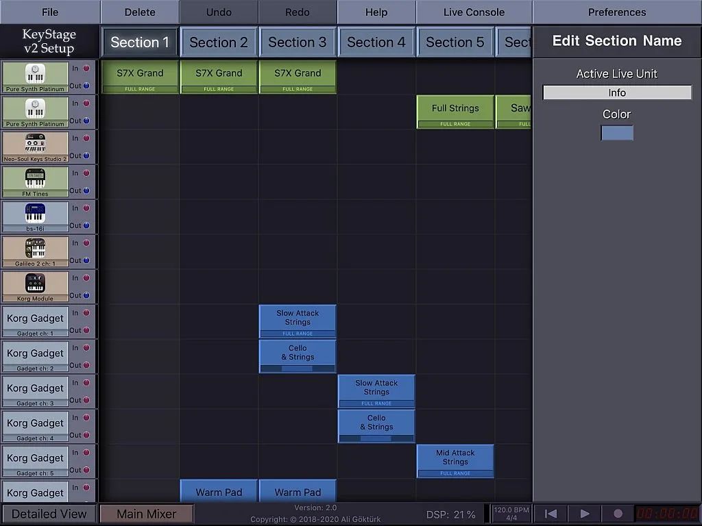
KeyStage supports external MIDI control so that instead of touching the display to switch sections, you can just press a button to move to another section of the song. Now, KeyStage requires a Momentary MIDI message. If you're going to use a Toggle button on it, you need to press the button twice to move to another section which is a hassle. So in this case, the ideal button to use is one that can transmit a Momentary MIDI message.
Now that we know the difference between Toggle and Momentary MIDI messages, let's check the code now. There are 10 tactile switches in this MIDI controller. I need to have both Toggle and Momentary buttons, so I have assigned switches 1-5 as momentary buttons and switches 6-10 as toggle buttons.
  /*--------------------------------------------------------------------------------------------------------*/
  /*THIS SECTION MAKES BUTTONS 1-5 MOMENTARY BUTTONS.*/
  // Check each button for the "falling" edge.
  // Send a Control Change message when each button presses
  // Update the Joystick buttons only upon changes.
  // falling = high (not pressed - voltage from pullup resistor)
  //           to low (pressed - button connects pin to ground)

  if (button0.fallingEdge()) {
    usbMIDI.sendControlChange(button0_CC, 127, channel);
  }
  if (button1.fallingEdge()) {
    usbMIDI.sendControlChange(button1_CC, 127, channel);
  }
  if (button2.fallingEdge()) {
    usbMIDI.sendControlChange(button2_CC, 127, channel);
  }
  if (button3.fallingEdge()) {
    usbMIDI.sendControlChange(button3_CC, 127, channel);
  }
  if (button4.fallingEdge()) {
    usbMIDI.sendControlChange(button4_CC, 127, channel);
  }

  // Check each button for "rising" edge
  // Send a MIDI Note Off message when each button releases
  // For many types of projects, you only care when the button
  // is pressed and the release isn't needed.
  // rising = low (pressed - button connects pin to ground)
  //          to high (not pressed - voltage from pullup resistor)

  if (button0.risingEdge()) {
    usbMIDI.sendControlChange(button0_CC, 0, channel);
  }
  if (button1.risingEdge()) {
    usbMIDI.sendControlChange(button1_CC, 0, channel);
  }
  if (button2.risingEdge()) {
    usbMIDI.sendControlChange(button2_CC, 0, channel);
  }
  if (button3.risingEdge()) {
    usbMIDI.sendControlChange(button3_CC, 0, channel);
  }
  if (button4.risingEdge()) {
    usbMIDI.sendControlChange(button4_CC, 0, channel);
  }
  /*--------------------------------------------------------------------------------------------------------*/
The code for switches 1-5 starts from line 105 and ends at line 151. There are three functions that we can notice here: myButton.fallingEdge();, myButton.risingEdge();, and usbMIDI.sendControlChange(control, value, channel);.
The myButton.fallingEdge(); function checks for a high to low transition. In this MIDI Controller, the internal pull-up resistors of the digital input pins of the Teensy 2.0 are enabled. So the pins are always in high condition when the switches are not pressed. The tactile switches are connected between the digital pins and ground. So if you're going to press the buttons, the digital pins are shorted to ground. The myButton.fallingEdge(); function detects this event.
The myButton.risingEdge(); function checks for a low to high transition. This event is when the condition of a digital pin changes from low to high because the button is released.
The usbMIDI.sendControlChange(control, value, channel); function allows the Teensy 2.0 to transmit a Control Change MIDI message. "control" is the controller number, "value" is the controller value, and "channel" is the MIDI channel.
  if (button0.fallingEdge()) {
    usbMIDI.sendControlChange(button0_CC, 127, channel);
  }
  if (button1.fallingEdge()) {
    usbMIDI.sendControlChange(button1_CC, 127, channel);
  }
  if (button2.fallingEdge()) {
    usbMIDI.sendControlChange(button2_CC, 127, channel);
  }
  if (button3.fallingEdge()) {
    usbMIDI.sendControlChange(button3_CC, 127, channel);
  }
  if (button4.fallingEdge()) {
    usbMIDI.sendControlChange(button4_CC, 127, channel);
  }
The if statements from line 113 to line 127 are all similar. They just differ in button number and controller number. These if statements check if there's a high to low transition on digital pins 0 to 4. If there's a transition, the usbMIDI.sendControlChange(control, value, channel); function is executed and the Teensy 2.0 transmits a Control Change MIDI message containing the controller number and 127 value at MIDI channel 1.
  if (button0.risingEdge()) {
    usbMIDI.sendControlChange(button0_CC, 0, channel);
  }
  if (button1.risingEdge()) {
    usbMIDI.sendControlChange(button1_CC, 0, channel);
  }
  if (button2.risingEdge()) {
    usbMIDI.sendControlChange(button2_CC, 0, channel);
  }
  if (button3.risingEdge()) {
    usbMIDI.sendControlChange(button3_CC, 0, channel);
  }
  if (button4.risingEdge()) {
    usbMIDI.sendControlChange(button4_CC, 0, channel);
  }
Since buttons 1 to 5 are Momentary buttons, if the buttons are released the Teensy 2.0 should send a value of 0. The if statements from line 136 to line 150 handle this task. When a button between digital pin 0 to 4 is released, there will be a low to high transition and one of these if statements detects this transition. A usbMIDI.sendControlChange(control, value, channel); function will be executed but this time, the value will be 0.
  /*--------------------------------------------------------------------------------------------------------*/
  /*UNCOMMENT THIS SECTION IF YOU WANT TO MAKE BUTTONS 1-5 TOGGLE BUTTONS AND COMMENT THE CODE FOR MOMENTARY BUTTON.*/
  /*if (button0.fallingEdge()) {
    b0 = ~b0;
    b0 = b0 & 0x7F;
    usbMIDI.sendControlChange(button0_CC, b0, channel);
  }
  if (button1.fallingEdge()) {
    b1 = ~b1;
    b1 = b1 & 0x7F;
    usbMIDI.sendControlChange(button1_CC, b1, channel);
  }
  if (button2.fallingEdge()) {
    b2 = ~b2;
    b2 = b2 & 0x7F;
    usbMIDI.sendControlChange(button2_CC, b2, channel);
  }
  if (button3.fallingEdge()) {
    b3 = ~b3;
    b3 = b3 & 0x7F;
    usbMIDI.sendControlChange(button3_CC, b3, channel);
  }
  if (button4.fallingEdge()) {
    b4 = ~b4;
    b4 = b4 & 0x7F;
    usbMIDI.sendControlChange(button4_CC, b4, channel);
  }*/
  /*--------------------------------------------------------------------------------------------------------*/
So we're done with the Momentary buttons. Let's proceed with the Toggle buttons, tactile switches 6 to 10. Line 153 to line 180 makes button 1 to 5 toggle buttons. However, this is disabled in this code. If you want to make button 1 to 5 toggle buttons, just uncomment these lines and comment lines 105 to 151.
  /*--------------------------------------------------------------------------------------------------------*/
  /*THIS SECTION MAKES BUTTONS 6-10 TOGGLE BUTTONS.*/
  if (button5.fallingEdge()) {
    b5 = ~b5;
    b5 = b5 & 0x7F;
    usbMIDI.sendControlChange(button5_CC, b5, channel);
  }
  if (button6.fallingEdge()) {
    b6 = ~b6;
    b6 = b6 & 0x7F;
    usbMIDI.sendControlChange(button6_CC, b6, channel);
  }
  if (button7.fallingEdge()) {
    b7 = ~b7;
    b7 = b7 & 0x7F;
    usbMIDI.sendControlChange(button7_CC, b7, channel);
  }
  if (button8.fallingEdge()) {
    b8 = ~b8;
    b8 = b8 & 0x7F;
    usbMIDI.sendControlChange(button8_CC, b8, channel);
  }
  if (button9.fallingEdge()) {
    b9 = ~b9;
    b9 = b9 & 0x7F;
    usbMIDI.sendControlChange(button9_CC, b9, channel);
  }

  /*--------------------------------------------------------------------------------------------------------*/
The code that makes switches 6 to 10 toggle buttons starts from line 182 and ends at line 210. As you can see, the code consists of if statements that are all similar. They just differ again in controller number and value. Since they’re just the same, let's just consider the if statement at line 184.
  if (button5.fallingEdge()) {
    b5 = ~b5;
    b5 = b5 & 0x7F;
    usbMIDI.sendControlChange(button5_CC, b5, channel);
  }
The if statement at line 184 checks a high to low transition at digital pin 5 or if button 6 is pressed. If button 6 is pressed, the usbMIDI.sendControlChange(button5_CC, b5, channel); is executed and the Teensy 2.0 transmits a Control Change MIDI message containing "button5_CC" controller number and "b5" value at MIDI channel "channel".
The "button5_CC" controller number is set to 22 in line 32. The "b5" value is initialized at 0 in line 43 and "channel" MIDI channel number is set to 1 in line 9. To see how we made button 6 a Toggle button, let's check line 185. Before the usbMIDI.sendControlChange(button5_CC, b5, channel); is executed, the value of b5, which is initially 0, is inverted at line 185. So in binary, the initial value of b5 is 00000000 and when it is inverted, b5's value is now 11111111. A button should send either 0 or 127. So if the value is not 0, we expect it to send 127. Since b5's value now is 255 (11111111 in binary), in line 186 we ANDed b5 with 0x7F (01111111 in binary) to get the 127 value. In line 187, the Teensy 2.0 transmits the Control Change MIDI message containing the controller number 22, a controller value of 127, at MIDI Channel 1.
After transmitting the MIDI message, the current value of b5 now is 127. The next time button 6 is pressed, the value of b5 will be inverted again and then ANDed with 0x7F (01111111 in binary). So 127 (01111111 in binary), if inverted will become 10000000. ANDed with 0x7F (01111111 in binary), b5 will become 00000000 or 0 in decimal. The Teensy 2.0 transmits a Control Change MIDI message again containing the controller number 22, a controller value of 0, at MIDI Channel 1. So that’s how we made buttons 6-10 Toggle buttons.
So we're done with the Momentary and Toggle buttons. Let's check the code for the potentiometers.
  /*--------------------------------------------------------------------------------------------------------*/

  // only check the analog inputs 50 times per second,
  // to prevent a flood of MIDI messages
  if (msec >= 20)
  {
    msec = 0;

    int n0 = analogRead(A0) / 8;
    int n1 = analogRead(A1) / 8;
    int n2 = analogRead(A2) / 8;
    int n3 = analogRead(A3) / 8;
    int n4 = analogRead(A4) / 8;

    // only transmit MIDI messages if analog input changed
    if (n0 != previousA0) {
      usbMIDI.sendControlChange(controllerA0, n0, channel);
      previousA0 = n0;
    }
    if (n1 != previousA1) {
      usbMIDI.sendControlChange(controllerA1, n1, channel);
      previousA1 = n1;
    }
    if (n2 != previousA2) {
      usbMIDI.sendControlChange(controllerA2, n2, channel);
      previousA2 = n2;
    }
    if (n3 != previousA3) {
      usbMIDI.sendControlChange(controllerA3, n3, channel);
      previousA3 = n3;
    }
    if (n4 != previousA4) {
      usbMIDI.sendControlChange(controllerA4, n4, channel);
      previousA4 = n4;
    }
  }
The code for the potentiometers starts at line 212 and ends at line 245. To prevent a flood of MIDI messages, line 214 makes the Teensy 2.0 check the analog inputs only 50 times per second. After that, the elapsedMillis variable "msec" is initialized to 0 again in line 216. In lines 218 to 222, the Teensy 2.0 reads its analog inputs A0 to A4 where the 5 potentiometers are connected using the analogRead() function. After reading the analog inputs, the values are compared to the previous values. Remember the values that we initialized in lines 57 to 61?
The purpose of comparing the present values to the previous values is so that the Teensy 2.0 will only transmit MIDI messages if there are changes in the analog inputs. If there are no changes, then the Teensy 2.0 will not transmit any message. But if the previous value is not the same with the current value, the Teensy will transmit a Control Change MIDI message. For example in line 226, "usbMIDI.sendControlChange(controllerA0, n0, channel);". Here the Teensy 2.0 will transmit a MIDI message containing "controllerA0" controller number which we set as 27 in line 50, controller value "n0" which is the reading at A0 analog pin divided by 8, at MIDI channel "channel" set to 1 in line 9.
The reading at the analog pin is divided by 8 since the resolution of the ADC of the Teensy 2.0 is 10-bit while the controller value is just up to 7-bit.
After transmitting a MIDI message, the current value read at the analog pins replaces the previous value. See lines 227, 231, 235, 239, and 243. The while (usbMIDI.read()) function in line 249 ignores incoming MIDI messages since the MIDI Controller should just discard incoming MIDI messages.
  // MIDI Controllers should discard incoming MIDI messages.
  // http://forum.pjrc.com/threads/...
  while (usbMIDI.read()) {
    // ignore incoming messages
  }
}
So that’s all for the code. I hope the explanation helps you understand how this MIDI Controller works and hopefully will help you when you create your own code for a different hardware design.
Programming
To upload the code to the Teensy device, you can just click the Verify button in the Arduino IDE:

After that, the Arduino IDE will open the Teensy Loader and this one will appear:

To program the Teensy board, you need to press the button on the Teensy board, and after that, it’s done!

Note: Be sure to set Board to the correct Teensy board you’re using and the USB Type to MIDI under the Tools menu to avoid errors in uploading the code.

PCB Design
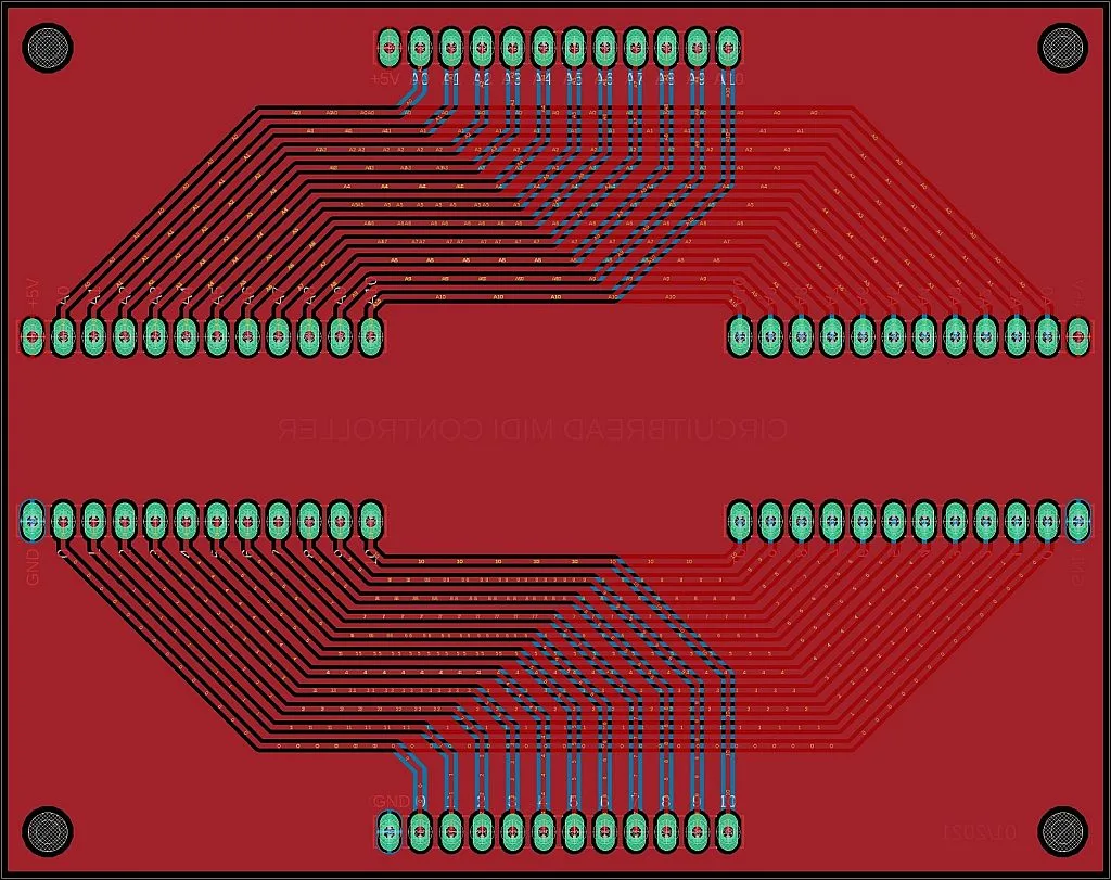
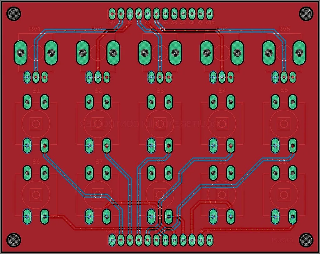
Gerber Files:
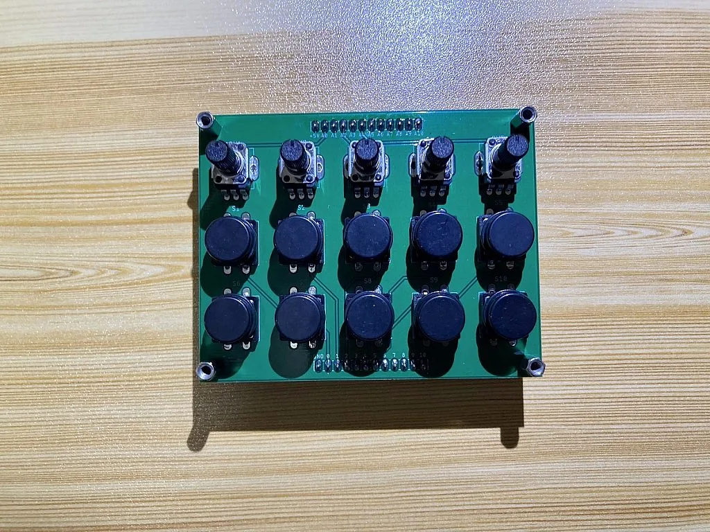
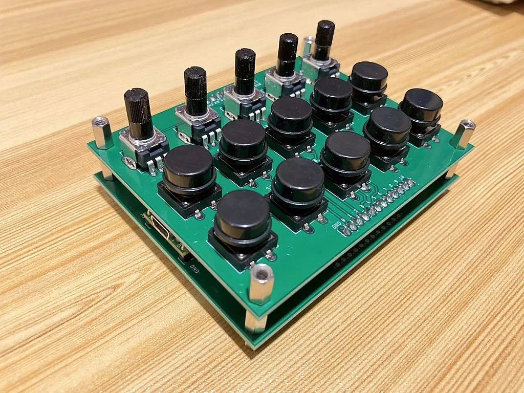
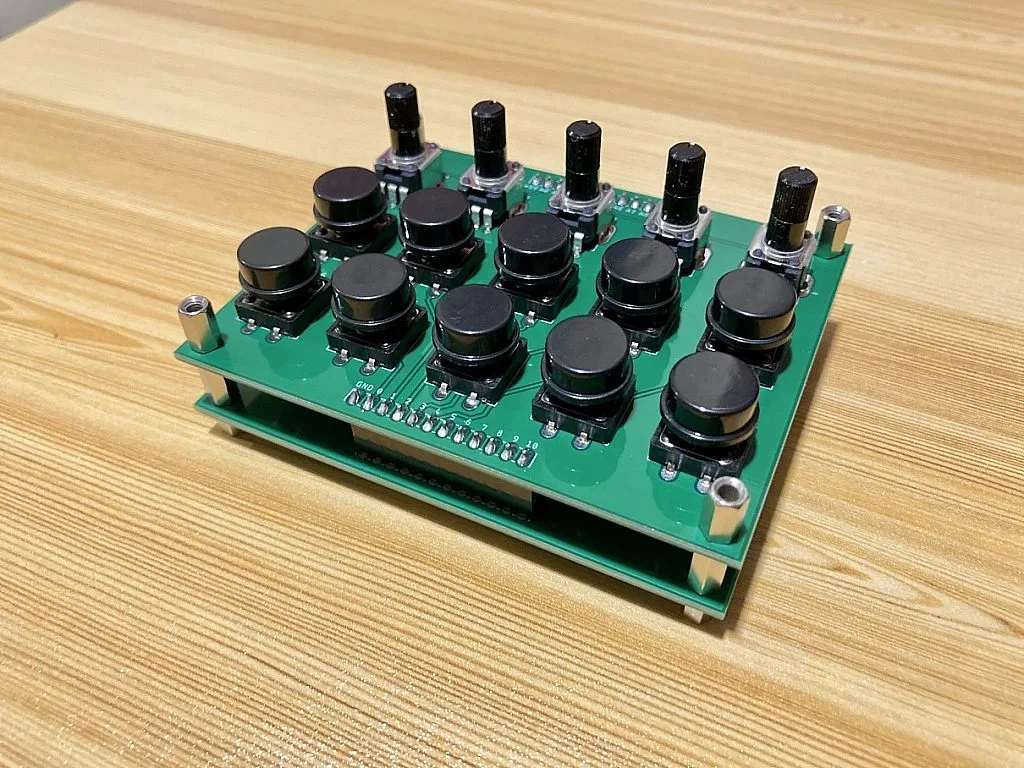
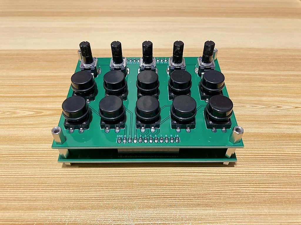
Actual PCB Images
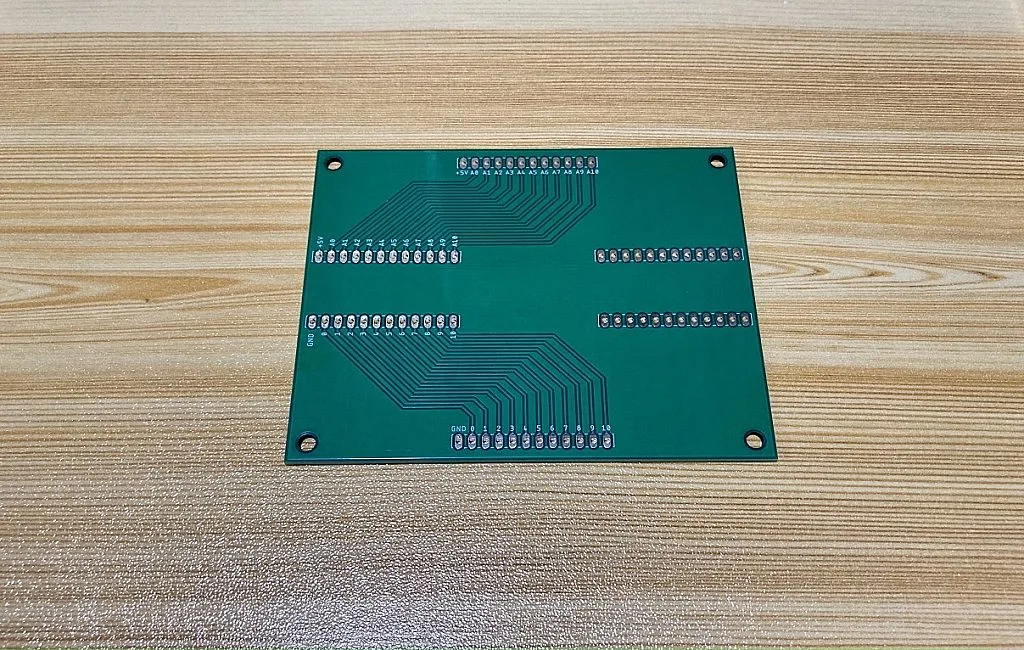
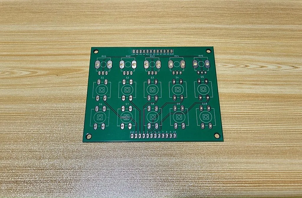
Assembled PCB
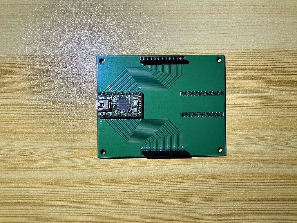
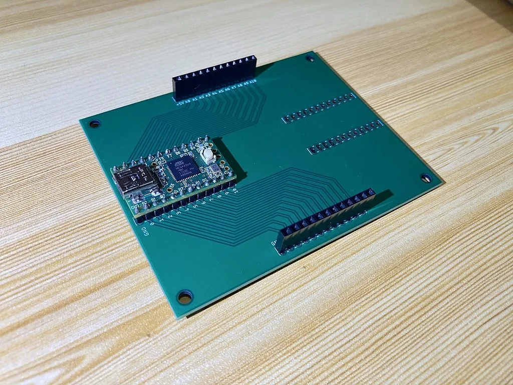
Enclosure
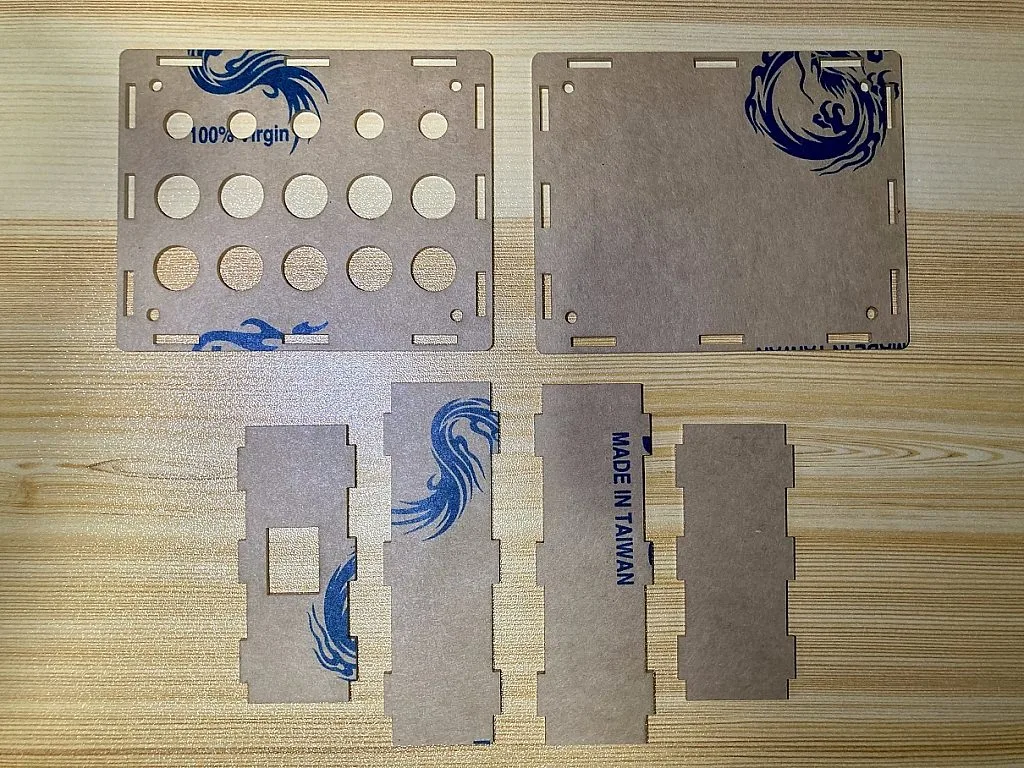
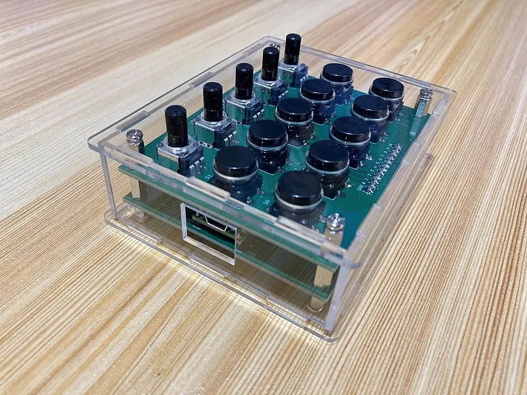
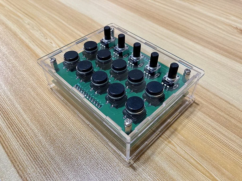
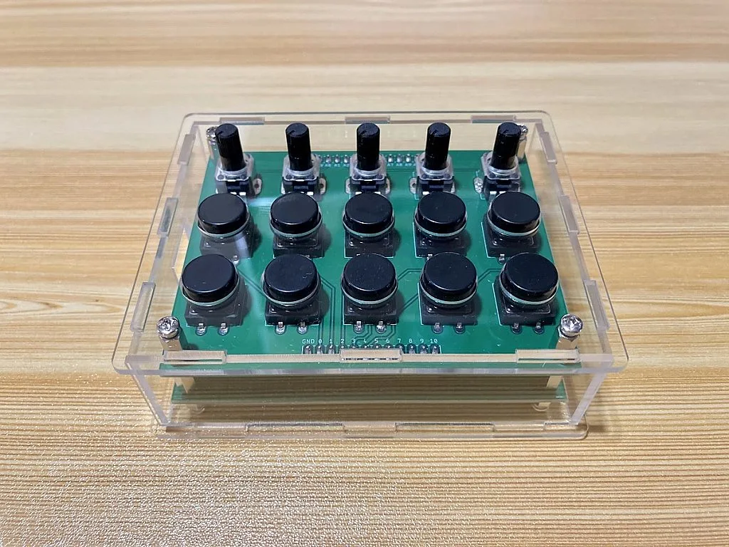
Enclosure DXF File: MIDI Controller Enclosure [2mm Acrylic Laser Cut]
Bill of Materials
| Part | Estimated Cost |
| 1. Teensy 2.0 | $24.01 at RS Components ($16 at PJRC Store) |
| 2. Potentiometers | $4.33 (5pcs at RS Components) |
| 3. Tactile Switches | ~$2 (10pcs. ordered from China) |
| 4. Male and Female Headers | ~$2 (ordered from China) |
| 5. PCB Standoff | ~6$ (M3 Standoff Spacer Kit ordered from China) |
| 6. PCB | $9.80 (Shipping fee not included. 5pcs 2 PCB designs. Ordered from Elecrow.) |
| 7. Enclosure | ~$5.16 |
| Estimated Total Cost | ~$53.30 |
Operating System (OS) Compatibility
Teensyduino implements a class compliant MIDI device. This means that Teensy boards can work with the built-in drivers on all major operating systems. So far I’ve tested this MIDI Controller on Windows 10 and iPadOS. But I think it will work well too on macOS and Android.
Testing the Teensy 2.0 MIDI Controller on Pocket MIDI

The Pocket MIDI is a free Windows 10 app that can monitor MIDI messages. On the MIDI In Monitor window, we can see the data or MIDI messages sent by the Teensy 2.0 when buttons 1 to 10 are pressed. Each of the MIDI messages sent by the Teensy 2.0 contains 3 bytes. As you can see, the first byte of all the MIDI messages is B0 or 1011 0000 in binary. The first nibble “1011” is the MIDI message name and the second nibble “0000” is the MIDI Channel Number. If you review the MIDI Channel messages table above, “1011” is Control Change and “0000” is MIDI Channel 1. This is what we set in our code using the line “const unsigned char channel = 1;” and the function “usbMIDI.sendControlChange(control, value, channel);”.
The second byte shows the control change number or the controller number in hex. You can check the code again to see the controller numbers that we’ve assigned to the button in decimal. The third or the last byte shows the control change value or controller value. Since buttons 1-5 are Momentary buttons, pressing and releasing the button makes the Teensy 2.0 transmit a value of 7F and 00 (hex) or 127 and 0 in decimal. For buttons 6-10, since they are Toggle buttons, we need to press the buttons twice in order to get a value of 127 and 0.

For the potentiometers or knobs, the data or MIDI messages transmitted by the Teensy 2.0 are almost the same as the buttons MIDI messages. The first byte contains the MIDI message name and MIDI channel number. The second byte contains the controller number. However, for the third byte, the controller value is not just 0 and 127. It can be any value from 0 to 127 depending on the position of the potentiometer’s shaft.
Check the Youtube video above to see the demo of the MIDI Controller Knobs and Buttons on Cubase (Windows 10), KeyStage (iPadOS), and AUM (iPadOS).
Summary
So that’s all! I hope you find this simple project interesting and helpful. If you’re a musician and at the same time an electronics hobbyist, I hope you find this MIDI Controller project helpful if you’re planning to create your own MIDI Controller. There are still a lot of things to improve in this MIDI Controller. For example, on the hardware side, you may like to use illuminated push buttons or LED compatible button pads to make your MIDI Controller more attractive and at the same time, it will be easier to see which buttons are enabled or disabled. But of course, expect that your MIDI Controller will be more expensive. You may also like to use or add faders or slide potentiometers, external inputs for footswitch and expression pedal. For the software, I think there is still a lot to improve too. You can improve the code to make the MIDI controller more responsive and you can add some features too. But so far, this current version works well for the simple applications that I use. If you have any questions regarding this project, comments, or suggestions, please feel free to leave a comment or contact us.

Get the latest tools and tutorials, fresh from the toaster.


