Renesas RA MCU “printf” function with a 1602 LCD | Renesas RA - 7
Published
Hello again! This time we will have a quite simple but useful tutorial. On the RenesasRulz forum there were several questions about how to connect a 1602 LCD to the RA MCU, and even more questions about how to redirect the “printf” function so it can send print to any display/interface. I spent several hours finding how to get it to work searching the information piece by piece from several sources. And now I will present it all to you in one place.
1602 LCD with the HD44780 Driver
I already mentioned the 1602 LCD in the PIC10F200 programming series. But that time I talked about it superficially, and now I will tell you about it in more detail.
There are several displays with the HD44780 driver, they can have different line numbers and position numbers (1x8, 2x8, 1x16, 2x16, 2x20, 4x20 etc.), also they can have different backlight colors (green, yellow, blue, etc.) or not have a backlight at all. The character’s color can be black or white. So, as you see, there is significant diversity but all of them have the same interface and are controlled using the same commands. I have the display shown in Figure 1 which I bought a long time ago on Aliexpress.
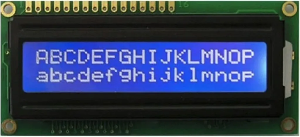
This LCD has a built-in character generator, so you don’t need to design your own characters (like we had to with the 7-segment indicator). We can just send the ‘A’ letter to the display, and it will be shown - fascinating, isn’t it? Also, the display has 16 empty cells in which you can load your own characters and then use them (I will talk about this later). The character generator of the LCDs from Aliexpress usually have a Chinese code page, so you can use the first 128 ASCII characters, which includes capital and small English letters, numbers, and punctuation signs which is quite good!
Let’s see which signals this display has (Figure 2).
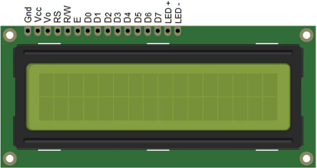
GND and VCC pins are the power supply of the display. Normally it is 5V but also can be 3.3V so be careful when buying an LCD.
The Vo pin is used to set the contrast of the LCD. Usually a potentiometer of 10-47 kOhm is connected to it.
RS is the data/command input. When this pin is low, the incoming data is considered as a command, and when it’s high, it is considered a character to display.
RW is the read/write input. When it is low, the data goes from the microcontroller to the LCD, and when it is high, the data goes the reverse direction. As we don’t expect any data from the LCD, we can connect this pin directly to ground.
E is the clock input. The data is read on the falling edge at this pin.
D0-D7 are the data inputs of the 8-bit parallel interface. The HD44780 driver also supports the 4-bit parallel interface. In this case, pins D0-D3 remain unused, and the bytes are transmitted by nibbles: higher one first, lower one second.
LED+ and LED- are the backlight power inputs. The supply voltage is also 5V, but a series resistor of 22-47 ohms is required.
As for the commands that the HD44780 uses, we didn’t consider them previously but now we will consider them in detail. I will base my explanations on the data sheet of the HD44780 driver, so you also can refer to it for full information. Let me present table 6 from the data sheet (Figure 3) where all the LCD commands are described.
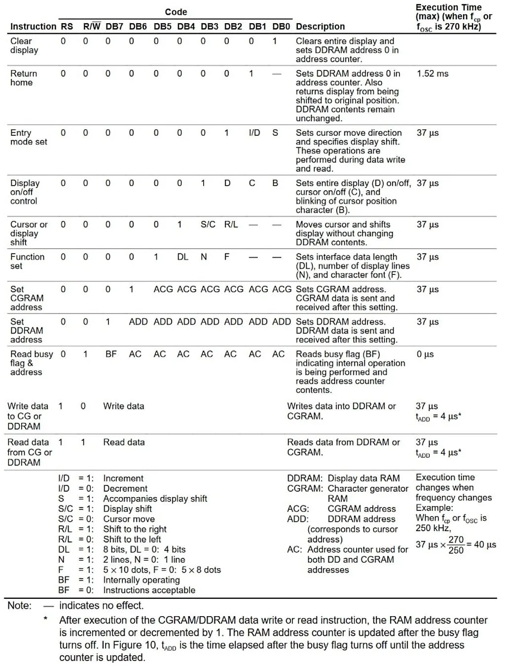
As you can see in Figure 3, the LCD has quite few commands, and each of them has at least one “1” in the data bits. Let me briefly run over all commands.
- “Clear display” command (0x01) seems to be quite clear (pun definitely intended): it clears the display content and sets the DDRAM counter to 0, so after this, the next character will be printed in the first position of the first line.
- “Return home” command (0x02) also clears the DDRAM counter to 0 but unlike the previous command, it doesn’t clear its content. Also if the shift was enabled for the display, the view returns to the initial position.
- “Entry mode set” command (0x04) has two parameters:
- I/D (bit #1) allows us to increment (if it is 1) or decrement (if it is 0) the DDRAM address which actually means if the text will be written left to right or right to left. For English text we need to set this parameter to 1 to write left to right.
- S (bit #0) allows us to shift the display leaving the cursor at the same position, when set to 1. The direction of the shift is set by the bit “S/C” of the command “Cursor or display shift”. When this bit is 0, no display shift occurs.
- “Display on/off control” command (0x08) has three parameters:
- D (bit #2) turns the display on when set to 1, and turns it off otherwise. The content of the DDRAM remains unchanged. So this bit just turns off the image, which can be restored instantly by setting it to 1.
- C (bit #1) enables (when it is 1) or disables (when it is 0) the cursor. The cursor is displayed in the 8’th line of the character (all characters have the size 5x7 pixels but the character place is 5x8 pixels, we will consider this later).
- B (bit #0) enables (when it is 1) or disables (when it is 0) the blinking of the overall position at the cursor. The blinking and the cursor can be enabled independently from each other, so you can select either any of them, or both, or none.
- “Cursor or display shift” command (0x10) has two parameters:
- S/C (bit #3) allows to shift the cursor by one position (the DDRAM counter also changes) if it is 0, or to shift the entire display (the counter remains the same) if it is 1. This option is useful to search the text in the display, or to implement the running line by the internal means of the display.
- R/L (bit #2) sets the direction of the shift: to the right when it is 1, or to the left when it is 0.
- “Function set” command (0x20) is one of the basic ones that needs to be implemented during the initialization process to allow the display to operate correctly. It has three parameters:
- DL (bit #4) sets the data bus width: 0 for 4 bits (in this case pins DB0-DB3 are not used, as I mentioned before), 1 for 8 bits (in this case all data pins are used).
- N (bit #3) sets the number of display lines: 0 for one line, and 1 for two lines.
- F (bit #2) sets the character font type: 0 for 5x8, 1 for 5x10. This parameter should be set according to the physical LCD type. The most widespread displays have the 5x8 characters, so we need to set this bit as 0.
- “Set CGRAM address” (0x40) sets the address of the character generator memory. This address has 6 bits width. I’ll explain this part in more detail later.
- “Set DDRAM address” (0x80) sets the address of the display data memory. This address has 7 bits width, and sets the position of the cursor at the LCD. Bit #6 sets the line number (0 – first line, 1 – second line), and bits #3-0 set the position within a line (0 to 15).
- “Read busy flag and address” commands allow reading the busy flag and address, as follows from its name. As we’re not going to use the reading option, I’ll let you delve into the details of this command on your own.
- “Write data to CG or DDRAM” command allows writing the data either to CGRAM or to DDRAM depending on the previous command: “Set CGRAM address” or “Set DDRAM address”, respectively.
- “Read data from CG or DDRAM” command allows reading from either CGRAM or DDRAM. As we’re not going to use the reading option, I’ll not consider this command any deeper either.
Now, let’s talk about the CGRAM. Let me copy table 5 from the datasheet (Figure 4) to illustrate how the generation of custom character happens.

I mentioned before there are sixteen DDRAM addresses in which you can locate the custom characters. But in fact, bit #3 in these addresses is not used (see Figure 4, column 1), so you can generate only eight custom characters.
As you can see from Figure 4 each character consists of eight lines. The lower three bits of the CGRAM address represent the number of a line within one character (top line first), and the upper three bits of the CGRAM address represent the number of the character. Also in the last column you can see that the upper three bits of the character generator are not used, and can be anything.
Let’s now try to generate a smiley face character and create the code for it (table 1).

We leave the upper three bits blank (which correspond to 0)4, and write the character only using the lower five bits. Also we leave the last line blank because this is the cursor position, so it’s better not to use it.
I think that’s all we need to know about the HD44780 driver to implement the given task, so let’s consider the schematics diagram of the LCD connection to the development board.
Schematic Diagram
The schematics diagram is presented in Figure 5.

This schematic diagram consists of the EK-RA2A1 board (J2) and the 1602 LCD (X1) which is connected as described above. The Vo pin is connected to the 10-47 kOhm potentiometer R1. When you power up the device, you should rotate the handle of the potentiometer to make the rectangles of the LCD barely visible. Then the contrast level is set correctly. The LED+ pin is connected to the VCC directly.
Attention! The EK-RA2A1 board has the supply voltage of 3.3V with the max current of 600 mA. So you need to either find the 1602 LCD that has the power supply of 3.3V, or to use an external 5V power source for the LCD. The only difference in the schematics diagram in this case will be that the LED+ pin is connected to VCC via a current-limiting resistor of 22-47 Ohm. Also, you must not connect the VCC pin of the board to the LCD.
The RS, E, D4, D5, D6, and D7 pins are connected to the MCU located on the development board. In Figure 5 the J2 connector pinout corresponds to the J2 connector located on the EK-RA2A1 board. Actually I’ve drawn only the part of the J2 connector as in fact it is 2x20 pins. And even among those fifteen pins that are present in Figure 5, only eight are used. You can notice that the connection seems to be kind of random. Well, this observation is very close to the truth. The thing is that some pins are already configured in the BSP of the board and can’t be changed from the peripheral mode to the general purpose IO mode. Other pins have internal connections which interfere with the external communications, so they can’t be used either. So what I did is just checked all the pins one by one in the FSP Configurator to make sure they can be used as GPIOs. Then I checked in the User’s Manual if the pins don’t have an internal connection, and only after that did I consider them as suitable options. In this way I selected pins P301, P302, P410, P015, P107, and P106 as you can see in Figure 5. Actually, you can connect any of them to any LCD pin, just don’t forget to configure them properly in the FSP Configurator.
That’s all that I wanted to tell you about the schematics diagram, let’s now proceed to the program part.
Project Configuration
Let’s create a new Renesas RA project with the “Bare Metal - Minimal” template and open the “Pins” tab of the FSP Configurator. This time it will be the only tab in which we will make the changes, as we don’t need anything but the GPIO.
We need to configure all pins that I mentioned in the previous chapter as outputs with the initial state low. The “Drive Capacity” may be left low, the “Output type” should be set as “CMOS”. Let’s see how it’s done with pin P410 to which the RS pin of the LCD is connected (Figure 6).
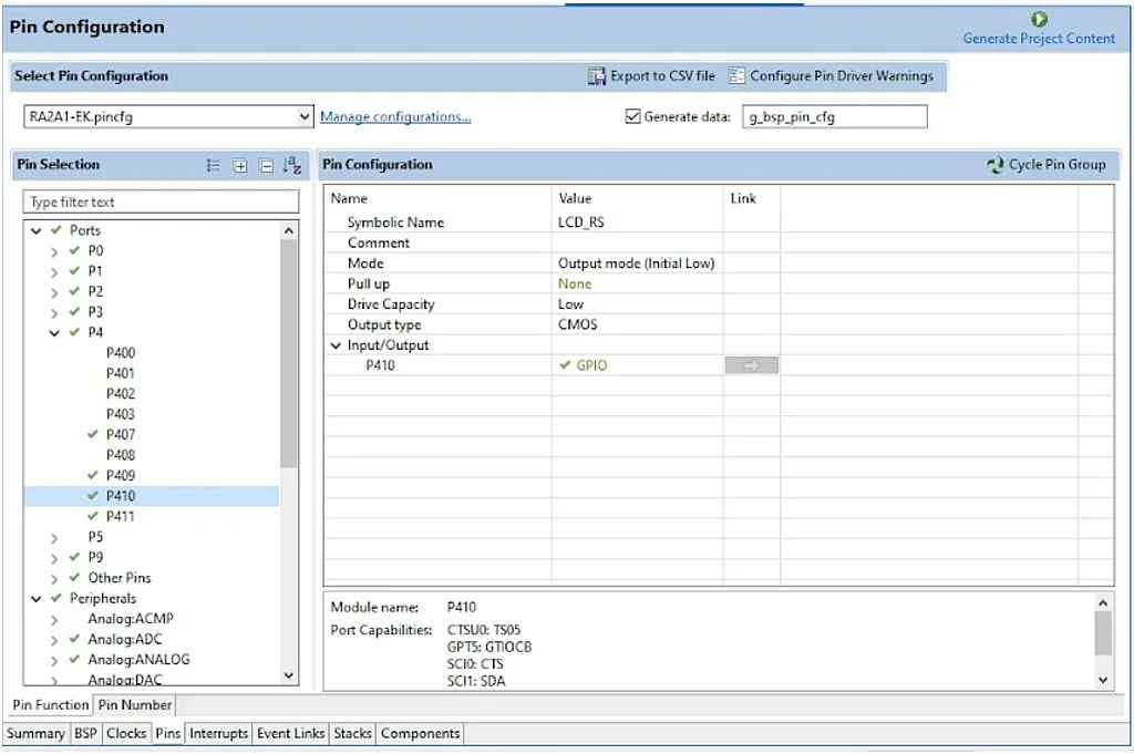
As you see, we gave the “Symbolic Name” of this pin as “LCD_RS”. It’s a useful feature, as now we can call this pin by this name in our code, not the neutral and long “BSP_IO_PORT_04_PIN_10” given by the FSP. As for the other settings, I explained them before. In the same way we need to configure the rest pins, just giving the following symbolic names to them: P015 - “LCD_E”, P106 - “LCD_D4”, P107 - “LCD_D5”, P301 - “LCD_D6”, P302 - “LCD_D7”.
After all this is done, click on the “Generate Project Content” button to generate the required code.
Now let’s move to the “Project Explorer” window in the left part of the window. Right-click on the “src” folder, and in the drop-down menu select the line “New” then “File” (Figure 7).
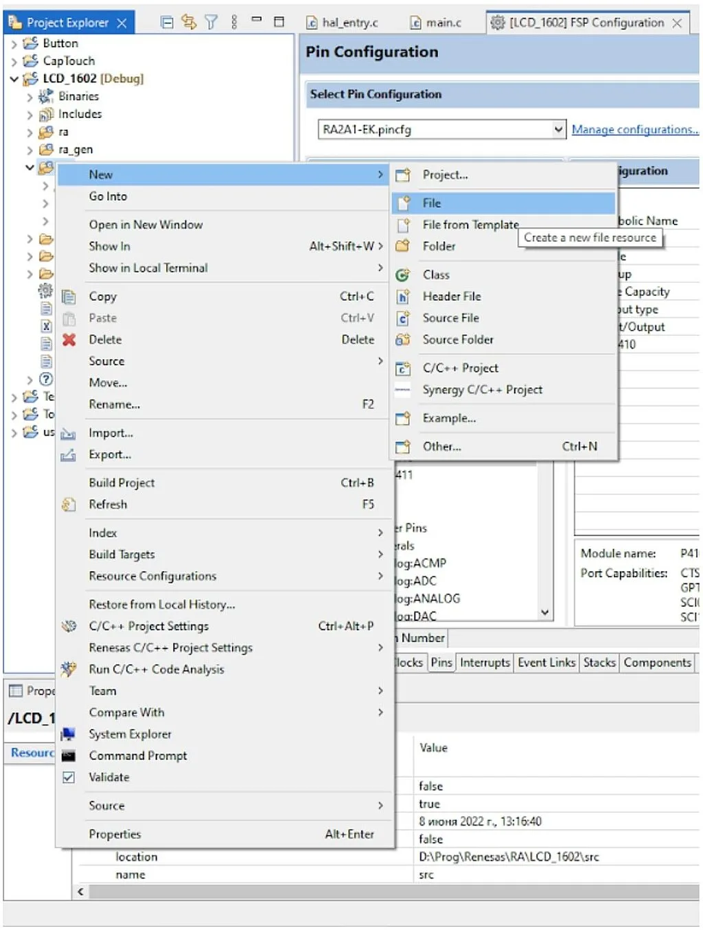
In the opened window we need to give the “File name”, for example “lcd1602.c” (Figure 8), then click the “Finish” button.

Then create one more file and call it “lcd1602.h”. These two files will contain the LCD specific functions, and can be copied to other projects in the future.
Now let’s open the “lcd1602.h” file and write the following text in it:
void lcd_send (uint8_t value, uint8_t rs);  	//Send any data to the LCD
void lcd_command (uint8_t command);         //Send the command to the LCD
void lcd_data (uint8_t data);               	//Send the character to the LCD
void lcd_init (uint8_t cursor, uint8_t blink);  //Initialize the LCD
void lcd_set_cursor (uint8_t x, uint8_t y); //Set cursor at the specified position
void lcd_create_char (uint8_t addr, uint8_t *data);//Create a custom character
This file contains the function definitions that we will use for operating with the LCD.
The lcd_send function (line 1) allows sending a byte of data to the LCD via a 4-bit interface. It has two parameters: value, which represents the byte that will be sent to the LCD, and rs which represents the state of the RS pin: 0 for low or 1 for high.
The lcd_command function (line 2) sends the command byte to the LCD, which is defined with the command parameter.
The lcd_data function (line 3) sends the character byte to the LCD, which is defined with the data parameter. This character will be sent either to CGRAM or to DDRAM.
The lcd_init function (line 4) initializes the LCD with the 4-bit interface. It has two parameters: cursor which shows (when it is 1) or hides (when it is 0) the cursor, and blink which enables (when it is 1) or disables (when it is 0) the blinking of the cursor position.
The lcd_set_cursor function (line 5) sets the cursor at the position defined by the parameters x and y.
The lcd_create_char function (line 6) creates one character in the CGRAM memory at the address defined by the addr parameter. Parameter data is the array of 8 bytes that define the character.
Well, that’s all about the functions definitions, let’s now consider their description in the “lcd1602.c” file:
#include "hal_data.h"
#include "lcd1602.h"


void lcd_send (uint8_t value, uint8_t rs)//Send any data to LCD
{
    R_BSP_PinAccessEnable(); 	//Enable access to the PFS registers
    R_BSP_PinWrite(LCD_RS, rs); //Set RS pin (data/command)
    R_BSP_PinWrite(LCD_E, 1);//Set E pin high to start the pulse
    R_BSP_PinWrite(LCD_D4, (value & 0x10) >> 4);//Assign bit#4 of the value to D4
    R_BSP_PinWrite(LCD_D5, (value & 0x20) >> 5);//Assign bit#5 of the value to D5
    R_BSP_PinWrite(LCD_D6, (value & 0x40) >> 6);//Assign bit#6 of the value to D6
    R_BSP_PinWrite(LCD_D7, (value & 0x80) >> 7);//Assign bit#7 of the value to D7
    R_BSP_SoftwareDelay(1, BSP_DELAY_UNITS_MICROSECONDS);//Delay needed by the driver
    R_BSP_PinWrite(LCD_E, 0);//Set E pin low to finish the pulse
    R_BSP_SoftwareDelay(1, BSP_DELAY_UNITS_MICROSECONDS);//Delay needed by the driver
    R_BSP_PinWrite(LCD_E, 1);//Set E pin high to start the pulse
    R_BSP_PinWrite(LCD_D4, (value & 0x01));//Assign bit#0 of the value to D4
    R_BSP_PinWrite(LCD_D5, (value & 0x02) >> 1);//Assign bit#1 of the value to D5
    R_BSP_PinWrite(LCD_D6, (value & 0x04) >> 2);//Assign bit#2 of the value to D6
    R_BSP_PinWrite(LCD_D7, (value & 0x08) >> 3);//Assign bit#3 of the value to D7
    R_BSP_SoftwareDelay(1, BSP_DELAY_UNITS_MICROSECONDS);//Delay needed by the driver
    R_BSP_PinWrite(LCD_E, 0);//Set E pin low to finish the pulse
    R_BSP_SoftwareDelay(40, BSP_DELAY_UNITS_MICROSECONDS);//Delay more than 37 us to implement the command
    R_BSP_PinAccessDisable();	//Disable access to the PFS registers
}


void lcd_command (uint8_t command)//Send command to LCD
{
    lcd_send(command, 0);   //Issue lcd_send function with RS = 0
}


void lcd_data (uint8_t data)//Send command to LCD
{
    lcd_send(data, 1);  	//Issue lcd_send function with RS = 1
}


void lcd_init (uint8_t cursor, uint8_t blink)  //Initialize LCD
{
    lcd_command(0x30);  	//Try to use 8-bit interface
    R_BSP_SoftwareDelay(4200, BSP_DELAY_UNITS_MICROSECONDS);//Delay for command implementation
    lcd_command(0x30);  	//Try 8-bit interface one more time
    lcd_command(0x28);  	//Set 4-bit interface, two lines
    lcd_command(0x08);  	//Turn off the display
    lcd_command(0x01);  	//Clear the display and reset the address to 0
    R_BSP_SoftwareDelay(4200, BSP_DELAY_UNITS_MICROSECONDS);//Delay for command implementation
    lcd_command(0x06);  	//Cursor move direction from left to right
    lcd_command(0x0C | (cursor << 1) | blink); //Turn on display, set the cursor and blinking parameters
}


void lcd_set_cursor (uint8_t x, uint8_t y) //Set cursor at the specified position
{
    if (y > 2)  	//If we try to set the line number more than 2
        y = 2;  	//Set the line #2
    if (x > 16) 	//If we try to set the position number more than 16
        x = 16; 	//Set the position #16
    lcd_command(0x80 | ((y - 1) << 6) | (x - 1)); //Set the cursor position at the LCD
}


void lcd_create_char (uint8_t addr, uint8_t *data) //Create a custom character
{
    if (addr > 7)  //If the address is higher than 7
        addr = 7;  //Then set address as 7
    lcd_command (0x40 | addr << 3); //Set the address of the CGRAM
    for (uint8_t i = 0; i < 8; i ++) //Loop to send all 8 bytes
    {
        lcd_data (data[i]); //Send data to LCD
    }
}
First, we include the “hal_data.h” header file (line 1) to use the FSP-generated functions in the current file. Then we include the “lcd1602.h” file (line 2). Actually, we don’t necessarily need to include it because we don’t use any definitions from that header in the current file. The rest of the file contains the functions code.
Let’s begin with the function lcd_send (lines 4-25). This is the most important function here and it implements the low-level communication between the MCU and LCD. To understand better how it works, let’s consider the part of the timing diagram from the figure 9 of the datasheet that corresponds to the writing cycle (Figure 9).

It’s not shown in Figure 9 but first you need to set the proper level at the RS pin (0 for command, 1 for data). This is what we do in line 7. Preliminary, we should enable access to the PFS registers (line 6), otherwise there will be no changes
Then in line 8 we start the pulse at the E pin. As you remember (and as follows from Figure 9) the data is latched at the falling edge of the E pulse.
Now we need to send the upper nibble of the value via the pins D4-D7. We will do this bit by bit. This is a different approach than in the previous tutorial but it gives more flexibility because it doesn’t require all data pins of the LCD to be connected to the consequent pins of the same port of the MCU.
In lines 9-12 we set the right level on the D4-D7 pins. Let’s consider these lines in more detail.
As you know, if we use a 4-bit interface, we first transmit the upper four bits of the data byte, so pin D4 corresponds to bit #4, pin D5 corresponds to bit #5, etc.
So in line 9 we check the fourth bit of the value by implementing the bitwise AND operation between the value and the 0x10 constant (0b00010000 in the binary system). The second parameter of the R_BSP_PinWrite function can accept two values: 0 or 1, so if the fourth bit of the value is 1, we need to shift it to the right by 4 bits to have 1 in the bit#0.
Then we do the same with bits #5-#7 (lines 10-12).
In line 13, we perform the short delay of 1us which is needed by the LCD driver. Actually the minimum length of the E pulse is 230 ns according to the data sheet, but as we’re not going to display dynamic information, 1us is fine.
In line 14, we set the E pin low to end the first E pulse. At this moment the data at the DB4-DB7 pins is read by the LCD driver.
Now we implement another 1us delay (line 15) which corresponds to pause between the E pulses (Figure 9), and start the next E pulse (line 16) to send the lower nibble of the data byte.
In lines 17-20, we check bits #3-#0 of the value and set the pins D7-D4 correspondingly, the same as we did in lines 11-26.
Then we need to implement a 1us pause (line 21) and set the E pin low to latch the data (line 22).
After that, we consider that the 8 bits of the data byte are sent to the LCD. Finally, we implement a 40us delay to complete the operation (line 23). According to the HD44780 driver data sheet the time of execution of most commands is 37us. So 40us is plenty of time for it to execute most of the commands. For the commands that need more execution time we will implement the additional delay beyond this function.
Finally, we disable access to the PFS registers to prevent random changes of the GPIO pins (line 24).
The lcd_command (lines 27-30) and lcd_data (lines 32-35) functions are very similar: they both consist of one line, in which the lcd_send function is invoked (lines 29 and 34). But in the lcd_command function the rs parameter is 0, and in the lcd_data function the rs parameter is 1. We could get rid of these functions and replace them with the lcd_send, which could do both functions, but using them makes the code more readable.
The lcd_init function (lines 37-48) initializes the LCD according to the routine suggested in Figure 24 of the datasheet of the HD44780 driver but with slight changes.
First we need to try to set the 8-bit data interface by sending the “Function set” 0x30 command (Figure 3) (line 39). Then we need to implement a delay of more than 4.1ms, so we implement the 4200us delay (line 40). After that we try to set the 8-bit data interface one more time by sending the 0x30 command (line 41). The datasheet recommends trying to set the 8-bit interface a third time, but even without doing this, it seems to work well.
Then we set the data interface of 4 bits and two display lines by sending the “Function set” 0x28 command (line 42). Next, we need to turn off the display by sending the “Display on/off control” 0x08 command (line 43). After that we issue the “Clear display” 0x01 command (line 44) and wait for another 4200us (line 45) because implementation of this command requires more time.
Then we send the “Entry mode set” 0x06 command (line 46) which will increment the address after each character, and thus set the text direction from left to right.
Finally we send the “Display on/off control” command one more time (line 47) but this time we turn the display on. Also, we send the values cursor and blink at the corresponding bits (#1 and #0, respectively) to set the cursor parameters.
And that’s about it for initializing the display. We can set more parameters if we’d like, such as auto-shifting of the display but we can do this separately if needed.
In lines 50-57 there is the lcd_set_cursor function. In this function we consider that the first cursor position has the coordinates [1;1] but as the physical coordinates inside the display start with 0, we will need to subtract 1 from each parameter.
First, we need to limit the coordinates if we accidentally set them too big. We check to see if the y is bigger than 2 (line 52) and in this case set it as 2 (line 53). Then we check if the x is bigger than 16 (line 54) and in this case set it as 16 (line 55). Then we send the “Set DDRAM address” command to set the proper cursor position x and y (line 56).
The last function, lcd_create_char, is located in lines 59-68. In this function we also first check if the address is bigger than 7 (line 61) and set it as 7 in this case (line 62). This is needed because there are only eight available custom characters with addresses 0 to 7.
In line 63, we send the “Set CGRAM address” command, in which we shift the addr parameter 3 bits to the left. This is needed because the last 3 bits set the line address within one character (see Figure 4). After that, we implement the for loop (line 64) inside which we send the 8 bytes to the LCD which will form the required character (line 66).
And those are all functions that are required for operation with the LCD in the current and following projects.
Now, let’s switch to the “hal_entry.c” file and write the following code into it.
#include "hal_data.h"
#include "lcd1602.h"
#include <stdio.h>


FSP_CPP_HEADER
void R_BSP_WarmStart(bsp_warm_start_event_t event);
FSP_CPP_FOOTER


const uint8_t smile[8] = {0x0E, 0x1F, 0x15, 0x1F, 0x15, 0x1B, 0x0E, 0x00}; //Array to generate the smiley character
uint8_t x, y;
int _write(int file, char *ptr, int len);


int _write(int file, char *ptr, int len)
{
    FSP_PARAMETER_NOT_USED(file);   //We don't use this parameter


for (int i = 0; i < len; i++)   //Loop to send all the characters
    {
        if (*ptr == '\r')       	//If character is CR
        {
        	x = 1;              	//Then set the x coordinate to the first position
        	lcd_set_cursor(x, y);   //And update the cursor position
        }
        else if (*ptr == '\n')  	//If character is LF
        {
        	if (y == 1)         	//If we are in the first line
                y = 2;          	//Then move to line 2
        	lcd_set_cursor(x, y);   //And update the cursor position
        }
        else                    	//In all other cases
        	lcd_data((uint8_t)*ptr);//Send the character to the LCD
        ptr++;                  	//And increment the pointer
    }


return len;                 	//Return the number of characters that were sent
}


/*******************************************************************************************************************//**
 * main() is generated by the RA Configuration editor and is used to generate threads if an RTOS is used.  This function
 * is called by main() when no RTOS is used.
 **********************************************************************************************************************/
void hal_entry(void)
{
    setvbuf (stdout, NULL, _IONBF, 2);  // Disable Output Buffering
    x = 1;  //Initial x coordinate
    y = 1;  //Initial y coordinate


/* TODO: add your own code here */
    lcd_init(0, 0);     	//Initialize the LCD without cursor and blinking
    lcd_create_char(1, smile);//Create a smile character
    lcd_set_cursor(x, y);   //Set cursor at the position 6,1
    printf("Hi Renesas from\r\n Circuitbread \1"); //Send the greeting text to the LCD


while(1);           	//Main loop of the program is empty


#if BSP_TZ_SECURE_BUILD
	/* Enter non-secure code */
    R_BSP_NonSecureEnter();
#endif
}


/*******************************************************************************************************************//**
 * This function is called at various points during the startup process.  This implementation uses the event that is
 * called right before main() to set up the pins.
 *
 * @param[in]  event	Where at in the start up process the code is currently at
 **********************************************************************************************************************/
void R_BSP_WarmStart(bsp_warm_start_event_t event)
{
    if (BSP_WARM_START_RESET == event)
    {
#if BSP_FEATURE_FLASH_LP_VERSION != 0
        /* Enable reading from data flash. */
        R_FACI_LP->DFLCTL = 1U;


/* Would normally have to wait tDSTOP(6us) for data flash recovery. Placing the enable here, before clock and
     	* C runtime initialization, should negate the need for a delay since the initialization will typically take more than 6us. */
#endif
    }


if (BSP_WARM_START_POST_C == event)
    {
    	/* C runtime environment and system clocks are setup. */


/* Configure pins. */
        R_IOPORT_Open (&g_ioport_ctrl, g_ioport.p_cfg);
    }
}


#if BSP_TZ_SECURE_BUILD


BSP_CMSE_NONSECURE_ENTRY void template_nonsecure_callable ();


/* Trustzone Secure Projects require at least one nonsecure callable function in order to build (Remove this if it is not required to build). */
BSP_CMSE_NONSECURE_ENTRY void template_nonsecure_callable ()
{


}


#endif
As usual, I highlighted the added lines with the green color.
In line 2 we include the “lcd1602.h” header file which is needed to use the LCD-related functions.
In line 3 we include the “stdio.h” file which consists of the declaration of the standard printf and setvbuf function which we will use in our program.
In line 9 we define the constant array smile of 8 elements of uint8_t type. This array will be used to generate the smiley character. If you look closely, you should notice that the elements of the array correspond to the values presented in table 1.
In line 10 we declare the variables x and y which represent the X and Y coordinates of the cursor, respectively.
In line 11 we declare the _write function which is located below, in lines 13-36. The meaning of this function should be considered in more detail. When you use the printf function, it first forms the array of characters, and then sends the formed array to some stream. The second action is performed by the _write function. By default it’s defined with the attribute __weak which means that it can be redefined somewhere else, and it will be implemented from this new place.
So this is what we do here: redefine the standard function _write so the printf function will use it to send the characters where we need to.
The name and the parameters of the _write function should be exactly the same as in line 11 to make it work properly. The first parameter file is the handle of the file to where the characters will be sent. In our case we don’t use any files, so this parameter will not be used. The next parameter *ptr is the pointer to the array of char which was formed before by the printf function, and now is ready to be sent. The last parameter len is the number of characters to be sent. The function _write returns the number of characters that actually have been sent.
Let’s consider the implementation of this function for our case. In line 15 we call the macro FSP_PARAMETER_NOT_USED to let the compiler know that we are not going to use the file parameter. You can find its implementation and the description in the “fsp_common_api.h” file:
/** This macro is used to suppress compiler messages about a parameter not being used in a function. The nice thing about using this implementation is that it does not take any extra RAM or ROM. */
#define FSP_PARAMETER_NOT_USED(p) (void) ((p))
So nothing will hurt it if you don’t use it, you will just have one extra warning.
In line 17 we start the loop to process the len number of characters. In our implementation of the function we will process two special characters: CR - carriage return (‘\r’) which returns the cursor to the first position of the current line, and LF - line feed (‘\n’) which moves the cursor to the next line but leaves the current X position.
So first we check if the current character is the ‘\r’ (line 19). In this case we set the x coordinate as 1 (line 21) and update the cursor position (line 22). Please pay attention to how we process the ptr variable. In the C language the array name is actually the pointer to the first its element, so the text *ptr is equal to the text ptr[i]. But as we accept the pointer as the parameter, let’s use the first option.
Next, we check if the current character is ‘\n’ (line 24). In this case if the current line is 1 (line 26) we set the current line as 2 (line 27) and update the cursor position (line 28).
In all other cases (line 30) we just send the line to the LCD by calling the lcd_data function (line 31).
Finally, we increment the ptr pointer (line 32). In the end of the function we return the len value (line 35) as we have processed exactly this number of characters.
Now let’s proceed to the hal_entry function (lines 42-60).
First, we call the setvbuf function to disable the output buffer (line 44). Oh, this was the last piece of the puzzle that allowed me to get everything to work. Without it, nothing was displayed. Let’s consider why that happened. The printf function actually sends the data not directly into the output stream stdout but into its buffer. When the buffer is full, the data is automatically flushed to the output. You can force buffer flushing by calling the flush function. There is another approach though, which we use here - to disable the buffer entirely. The first parameter is the pointer to the FILE structure. In our case it’s the standard output stdout. The second parameter is the pointer to the user-defined buffer. As we are not going to use any buffer, we are free to write NULL here. The third parameter is the buffering mode. _IONBF means that no buffer will be used. And the final parameter is the buffer length. The minimum acceptable value of it is 2, so we write this value. If you want to know more about this function, you can refer to this page https://docs.microsoft.com/en-us/cpp/c-runtime-library/reference/setvbuf?view=msvc-170.
In lines 45 and 46 we set both cursor coordinates as 1.
In line 49 we initialize the LCD without the visible cursor and without the blinking. Next, we create the new character using the smile array (line 50) and save it at address 1. In line 51 we set the cursor to the initial position. Finally, in line 52 we print the greeting text on the LCD. Please note that we use both ‘\r’ and ‘\n’ characters. Also in the end of the text you can see the ‘\1’ character. If the number follows the backslash, this means that we want to print the character with the address defined by this number. So the expression ‘\1’ means the character at address 1, which is the smiley that we defined in line 9.
In line 54 there is the main loop of the program which is empty now because we don’t need to do anything as a cycle in our program.
Before proceeding to the practical work, we need to do two more things to make the printf function work as we desire.
First, in the Project Explorer window we need to right-click on the project name and select the last line of the drop-down menu “Properties”. In the opened window you need to expand the “C/C++ Build” list in the left part and select the “Settings” line. In the center of the window you should select the “Miscellaneous” line of the “GNU Arm Cross C Linker” list (Figure 10).
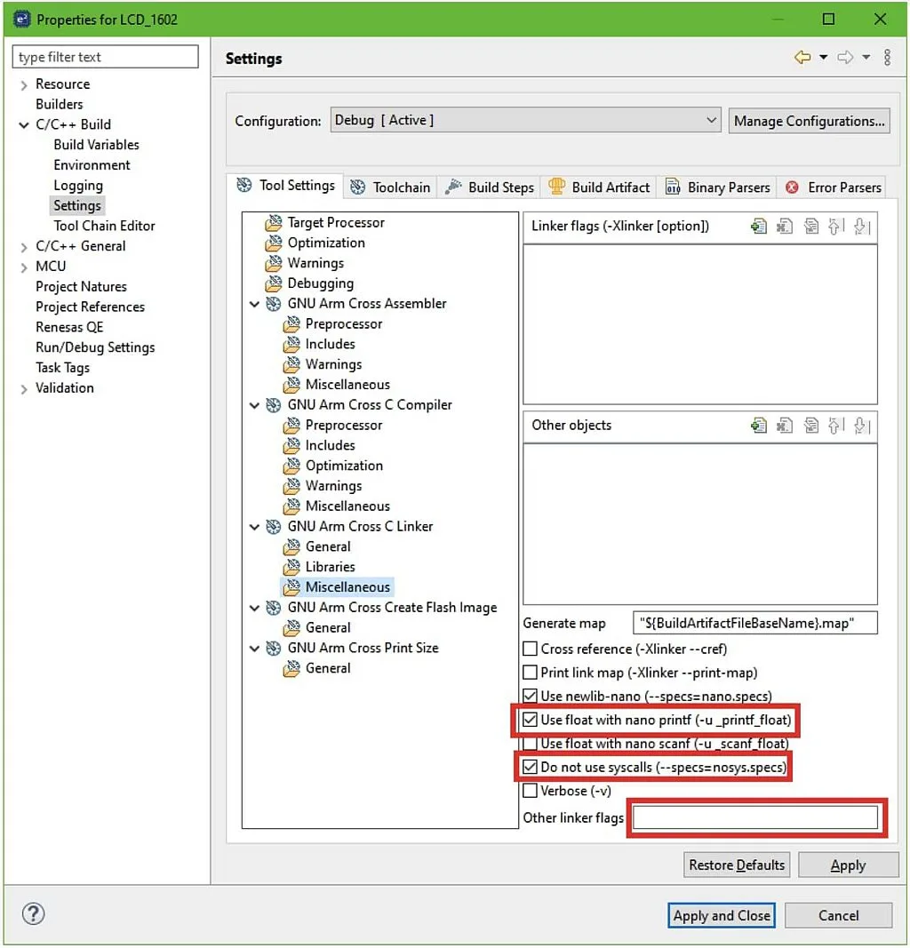
First, we need to clear the field “Other linker flags”. The default linker setting of “--specs=rdimon.specs” is a semihosted version of the C runtime library which means that the _write function will be replaced by the one defined in the runtime library not by our own. So we need to select the check “Do not use syscalls (--specs = nosys.specs)”. Now the syscall functions stubs (including _write) will be overridden by our own.
If you are going to display the floating point numbers using the printf function, you can select the check “Use float with nano printf (-u _printf_float)”. I will show you how this works later.
And the second setting to be changed is the heap size, as in its operation printf function uses the heap, and its default size is 0. To change it, let’s return to the FSP Configurator and open the “BSP” tab. In the “Properties” window in the left bottom corner find the “Heap size (bytes)” line under the “RA Common” list, and change its value to 0x1000 (Figure 11).

Don’t forget to click on the “Generate Project Content” one more time to make the changes in the program code.
And now let’s connect the board to the USB port of the PC, build the project and make sure that there are no errors, just some warnings. And finally start the debugging process and run the program. If you have connected everything properly, you should see the following (Figure 12).

If you don’t see anything or the text is very pale, try to rotate the handle of the potentiometer R1 to adjust the contrast. If you still don’t see anything, check the communications between the LCD and the development board.
Now, let’s see how the floating point numbers are displayed. Let’s adjust our program in the following way.
#include "hal_data.h"
#include "lcd1602.h"
#include <stdio.h>
#include <math.h>
void hal_entry(void)
{
    setvbuf (stdout, NULL, _IONBF, 2);  // Disable Output Buffering
    x = 1;  //Initial x coordinate
    y = 1;  //Initial y coordinate


/* TODO: add your own code here */
    lcd_init(0, 0);     	//Initialize the LCD without cursor and blinking
    lcd_create_char(1, smile);//Create a smile character
    lcd_set_cursor(x, y);   //Set cursor at the position 6,1
printf("pi=%6.4f\r\ne=%6.4f", M_PI, M_E); //Display the pi and e values
while(1); //Main loop of the program is empty
Here I highlighted the newly added lines with the yellow color. So first we need to include the “math.h” file to be able to use the M_PI and M_E macros. Actually we could define the π and the e values manually but we are not searching for the easy methods.
So in line 53 we use the printf function in which we display the π value with 4 fractional digits in the first line, and the e value with 4 fractional digits in the second line.
When you try to build the project it will give the error that the M_PI and M_E values are not defined. To fix this issue we need to open the project properties again but this time select the “Optimization” line under the “GNU Arm Cross C Compiler” list (Figure 13).
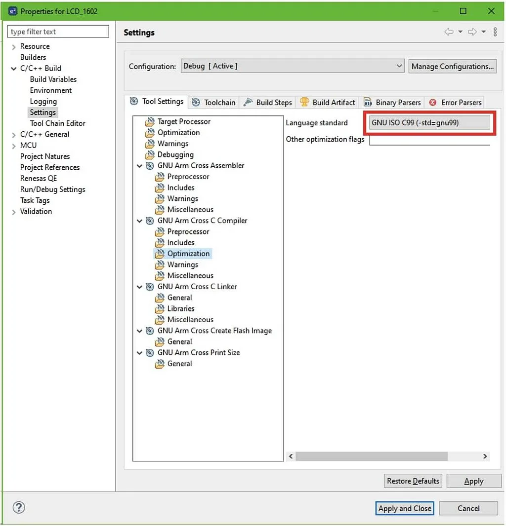
In the right part of the window you need to change the “Language Standard” from “ISO C99” to “GNU ISO C99”. After that everything will be fine.
When you run the program, you will see the following (Figure 14).

And that’s finally all I wanted to tell you in this tutorial. And that’s even more than I expected initially.
As homework, I suggest you add the support of the ‘\t’ character as the tabulation sign that will divide the line into four sections by four positions and move the cursor to the beginning of the next section.

Get the latest tools and tutorials, fresh from the toaster.


