What Are Interrupts and How Do They Work? | Renesas RL78 - 5
Published
Hi! Welcome back again to CircuitBread. In our previous tutorial, we discussed RL78 GPIOs and reviewed the code in our first project. I hope you have successfully programmed the 8 LED chaser without looking at my code. In this tutorial, we are going to discuss interrupts or interrupt functions.
Interrupt function is definitely not a beginner-level topic. However, we need to discuss it now because most of the RL78 peripherals generate an interrupt. But don’t worry, we will not discuss all of the interrupt sources in this tutorial. We will just use one to demonstrate how it works and as we discuss other peripherals in future tutorials, we will also show how to handle the interrupt generated by those peripherals.
Polling vs Interrupt
Let’s say we have nine tasks and one of these tasks requires special attention. We need to monitor the signal (flag/bit set to 1) that it provides so that the CPU can immediately perform the tasks under it.
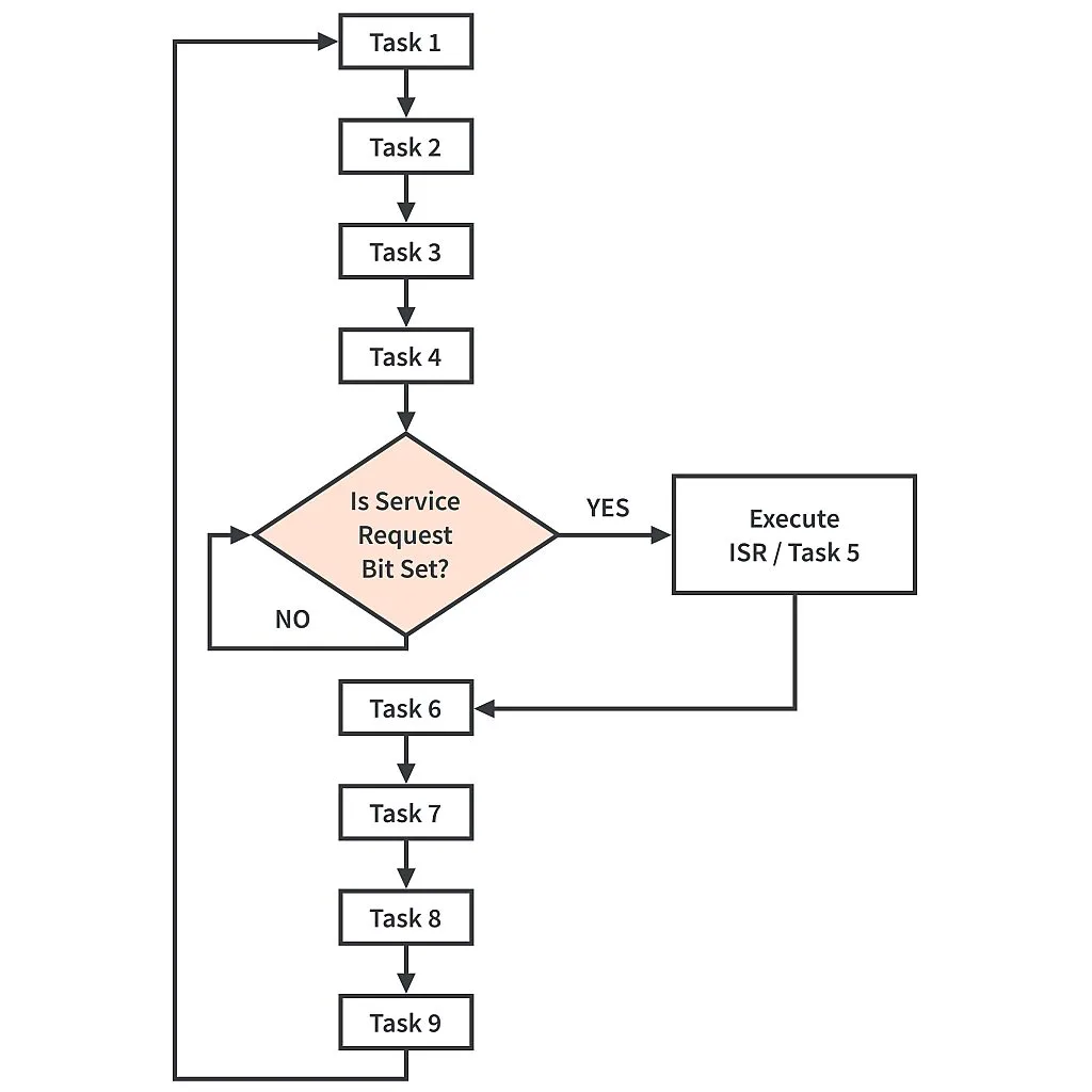
In polling, whether it’s blocking or non-blocking mode, the CPU will check first if the request flag/bit is already set before it executes an important task. Figure 1 shows an example of a blocking mode polling flowchart. As you can see, tasks 1 to 4 are executed first and after executing task 4, the CPU will check if the request flag/bit is set to 1. If it’s not, then the CPU will wait until the request flag/bit is set to 1 before proceeding to task 6. As you can see in this example, the disadvantages here are: 1) The CPU will execute first tasks 1 to 4 before checking the more important task. What if, during task 1 or 2, the request flag/bit was already set to 1? So there will be a delay before the more important task is executed. 2) If the request flag/bit is not yet set, then the CPU will still need to wait before it can execute the important task and proceed to tasks 6 to 9.
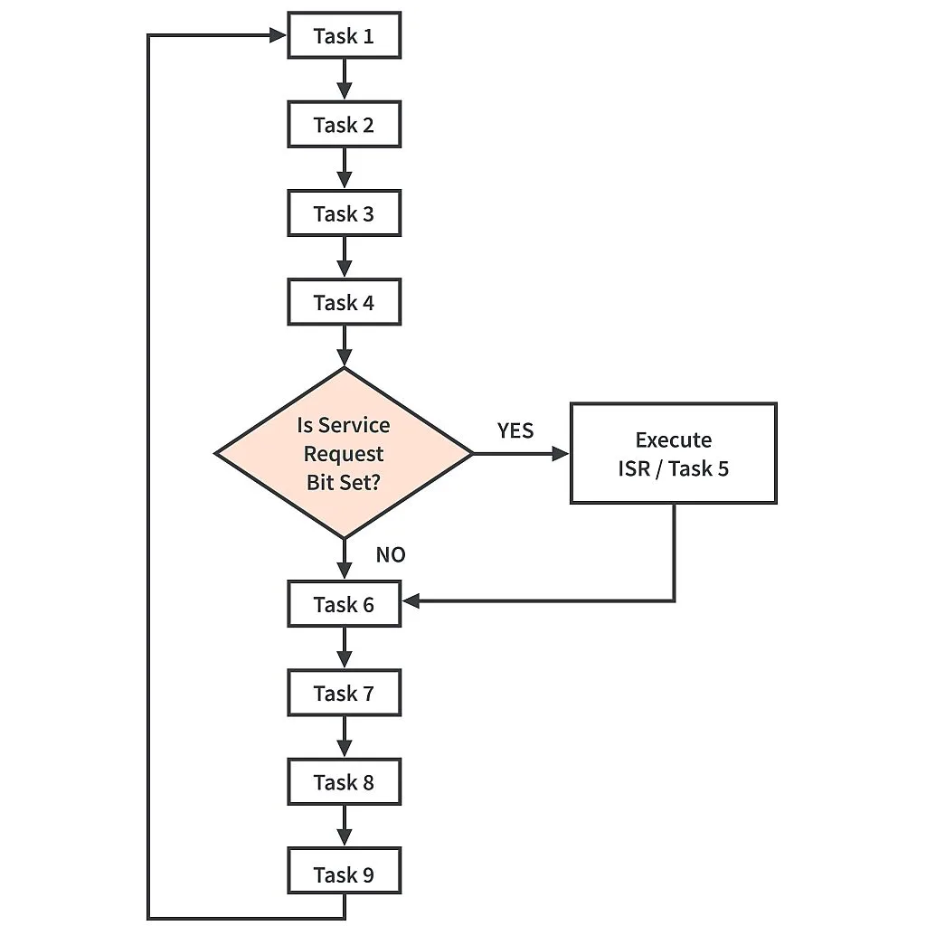
Figure 2 shows an example of a non-blocking mode polling flowchart and its advantage compared to blocking mode is that the CPU will proceed to the other tasks if the request flag/bit is not yet set. But the delay of executing the more important task is longer. Let’s say the request flag/bit was set while the CPU is executing task 6. Then, the CPU will still need to execute tasks 7-9 and tasks 1-4 again before it executes the important task.
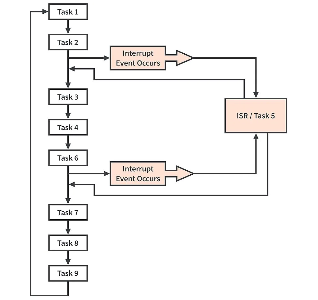
Interrupts overcome the limitations of polling. If interrupts are enabled and the peripheral used in a task generates an interrupt, the CPU doesn’t need to monitor the request flag/bit anymore. When an interrupt event occurs, once the CPU is done with the current instruction, the program then jumps to the assigned interrupt service routine (ISR) of that interrupt. After executing the ISR, the program will return to the instruction or task where it was interrupted. Using interrupts makes our code efficient and important tasks are executed faster.
Interrupt Sources, Types, and Configurations
The number of interrupt sources in RL78 MCUs depends on the number of pins of the device. In the RL78/G14, there are at least 30 maskable interrupt sources in MCUs with the smallest number of pins (30-pins). You can check table 21-1 to table 21-4 of the RL78/G14 hardware user’s manual for the list of interrupt sources and their types.
There are two types of interrupt functions used in RL78 MCUs, Maskable/Non-Maskable Interrupts and Software Interrupts.
- Maskable interrupts are interrupts that can be enabled or disabled by clearing or setting the interrupt mask flag registers, respectively. Disabling interrupts is usually done during hardware initialization to avoid problems. Once hardware initialization is done, interrupts are enabled again. Non-Maskable interrupts are interrupts that can’t be disabled and ignored by the CPU because they are very important. Examples of non-maskable interrupt sources are reset on reset pin input, overflow of the watchdog timer (WDT), low voltage detection, etc.
- Software Interrupt is generated when the BRK instruction is executed. It can’t be disabled and doesn’t undergo interrupt priority control. Even if interrupts are disabled, the software interrupt is still acknowledged and the program will jump to its ISR when this instruction is executed.
There might be more or less configurations in other RL78 MCUs, but in an RL78/G14 MCU, there are four basic interrupt configurations: internal, external (INTPn) , external (INTKR), and software configuration.
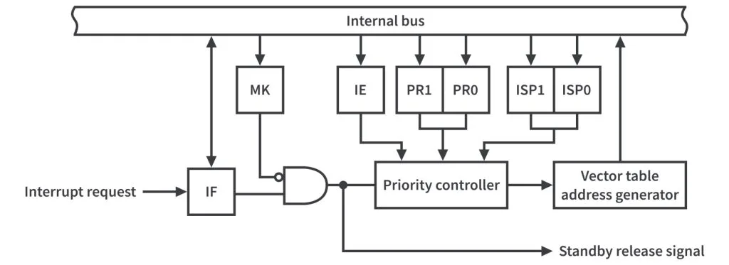
Internal interrupts are generated by peripherals for example when the ADC is done converting or the UART is done transferring data. You can check table 21-1 to table 21-4 of the RL78/G14 hardware user’s manual which interrupt sources have this kind of configuration. As shown in figure 4, in order to use an internal interrupt, we need to set or clear these flags, which we will discuss momentarily: IF, MK, IE, PR0, PR1, ISP0, and ISP1.

External interrupts are generated by inputting a rising or falling edge (or both depending on the EGP and EGN settings) to the external interrupt input pins INTPn or a falling edge to the key interrupt input pins KRn. External interrupt configurations are similar to internal interrupt configuration except that there are additional registers that we need to set or clear, EGP and EGN registers for external interrupt pins (see figure 5), and KRM register for key interrupt pins (see figure 6). The external interrupt and key interrupt pins are almost similar but I think the key interrupt function is more suitable for reading a key matrix.

The software interrupt has a very simple configuration. As shown in figure 7, only an interrupt request is needed for it to be processed. You don’t need to set or clear any registers.
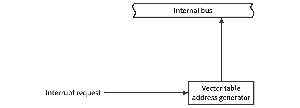
Registers Controlling Interrupt Functions
As mentioned earlier, in order to use an interrupt function, we need to set or clear some flags and registers that control it.
- Interrupt Enable Flag
IE
TheIEflag which is in the program status wordPSWregister is used to enable or disable all of the maskable interrupts in the RL78 MCU. If you clear this flag, you won’t be able to use any maskable interrupt functions. In our first project, if you follow the hardware initialization steps by clicking theStep Intobutton or pressing theF5function key, you will notice theDI()andEI()functions which disables and enables theIEflag, respectively. After reset, the value of theIEflag is0.

- Interrupt Request Flag
IF
When there’s a request from an interrupt source, theIFof that interrupt source is set to1. According to the hardware user’s manual, theIFcan also be set to1by executing an instruction. For now, I can’t think of a situation where we need to set theIFthrough software so let’s just ignore it for now.
| XXIFX | Interrupt Request Flag |
| 0 | No interrupt request signal is generated |
| 1 | Interrupt request is generated, interrupt request status |
- When the
IFis set to1and the CPU acknowledges the interrupt, the program then jumps to the interrupt service routine. If there’s a situation where we need to disable or mask an interrupt, theIFcan still be accessed by software to check if there’s a request. TheIFsare located in these registers:IF0L,IF0H,IF1L,IF1H,IF2L,IF2H(check chapter 21.3.1 of the RL78/G14 hardware user’s manual).
You can set or clear anIFusing a 1-bit memory manipulation instruction or set the entire interrupt request flag register using an 8-bit memory manipulation instruction. You can also use a 16-bit memory manipulation instruction if you combine theLandHregisters, for exampleIF0L and IF0H → IF0. A reset signal clears the interrupt request flag registers to00H(hex).
- Interrupt Mask Flag
MK
| XXMKX | Interrupt Servicing Control |
| 0 | Interrupt Servicing Enabled |
| 1 | Interrupt Servicing Disabled |
- If an interrupt is maskable, we can mask or disable the interrupt by setting its
MKflag to 1. By clearing (write0to it) theMKflag, the interrupt is enabled. TheMKflags are located in these registers:MK0L,MK0H,MK1L,MK1H,MK2L,MK2H(check chapter 21.3.2 of the RL78/G14 hardware user’s manual). AnMKflag can be set using a 1-bit memory manipulation instruction or you can set the entire interrupt mask flag register using an 8-bit memory manipulation instruction. You can also use a 16-bit memory manipulation instruction if you combine theLandHregisters, for exampleMK0L and MK0H → MK0. A reset signal sets the interrupt request flag registers toFFH(hex).
- Priority Specification Flags
PR0 and PR1
We prioritize important tasks by using interrupts. However, in RL78 MCUs or even in other MCUs, there are a lot of interrupt sources and if they occur simultaneously, the CPU will respond first to the interrupt with higher priority level.
ThePR0andPR1flags set the priority level of an interrupt source and since there are two flags, it means that we can set the priority level of an interrupt to one of four levels,00(level 0 - high priority level),01(level 1),10(level 2),11(level 3 - low priority level).
| XXPR1X | XXPR0X | Priority level selection |
| 0 | 0 | Specify level 0 (high priority level) |
| 0 | 1 | Specify level 1 |
| 1 | 0 | Specify level 2 |
| 1 | 1 | Specify level 3 (low priority level) |
- But what if two or more interrupt sources with the same priority level occur at the same time? In this case, the CPU will respond to the interrupt source with a lower default priority number. You can check the default priority number of an interrupt source in table 21-1 to table 21-4 of the RL78/G14 hardware user’s manual.
The priority specification flags of an interrupt source are located in these registers:PR00L,PR00H,PR01L,PR01H,PR02L,PR02H,PR10L,PR10H,PR11L,PR11H,PR12L,PR12H(chapter 21.3.3 of the RL78/G14 hardware user’s manual) or I think it is easier to identify the priority specification flags of an interrupt source by checking table 21-5 to table 21-8 of the RL78/G14 hardware user’s manual. Again, thePR0andPR1flags can be set using a 1-bit memory manipulation instruction or you can set the priority specification flag registers using 8-bit memory manipulation instruction. TheLandHregisters can be also combined and set using a 16-bit memory manipulation instruction, for examplePR00L and PR00H → PR00. A reset signal sets priority specification flag registers toFFH(hex).
- In-Service Priority Flags
ISP0 and ISP1
While thePR0andPR1flags set the priority level of an interrupt source, theISP0andISP1which are located in the program status wordPSWregister set the current interrupt priority level of the CPU.
| ISP1 | ISP0 | Priority of interrupt currently being serviced |
| 0 | 0 | Enables interrupt of level 0 (while interrupt of level 1 or 0 is being serviced) |
| 0 | 1 | Enables interrupt of level 0 and 1 (while interrupt of level 2 is being serviced) |
| 1 | 0 | Enables interrupt of level 0 to 2 (while interrupt of level 3 is being serviced) |
| 1 | 1 | Enables all interrupts (waits for acknowledgment of an interrupt) |
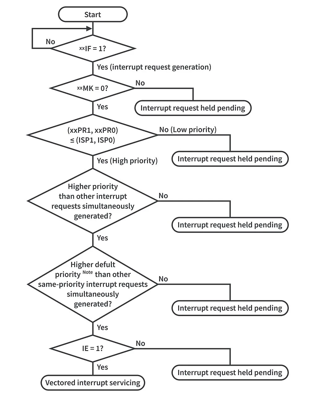
- As you can see in figure 8, if the value of the priority level of an interrupt source (set by
PR0andPR1flags) is greater than the value of theISP0andISP1flags, the CPU will ignore that interrupt source. In other words, if the priority level of an interrupt source is lower than what is set by theISP0andISP1flags, the CPU will just ignore the interrupt. For example, ifISP1andISP0is set to10, all level 3 interrupts will be ignored, only level 0 to 2 interrupt sources will be processed. After reset, the value ofISP1andISP0is11. So by default, all interrupt levels are acknowledged.
Since our example in this tutorial uses an external interrupt pin, we will add these two registers to our discussion: External interrupt rising edge enable registers EGP0, EGP1 and External interrupt falling edge enable registers EGN0, EGN1.
The detection enable bits, EGPn and EGNn (n = 0 to 11), which sets what type of edge will generate an external interrupt are located in the EGP0, EGP1 and EGN0, EGN1 registers, respectively. The table below shows what value should we write the detection enable bits to disable edge detection or detect a falling edge, a rising edge, or both.
| EGPn | EGNn | INTPn pin valid edge selection (n = 0 to 11) |
| 0 | 0 | Edge detection disabled |
| 0 | 1 | Falling edge |
| 1 | 0 | Rising edge |
| 1 | 1 | Both rising and falling edges |
RL78 MCUs can have up to 12 external interrupt pins depending on the number of the MCU pins. You can check table 21-9 of the RL78/G14 hardware user’s manual to see the detection enable bits of the external interrupts.
After reset, the default value of EGP0, EGP1 and EGN0, EGN1 registers are 00H (hex). So when using external interrupts, the detection enable bits should be configured because by default, edge detection is disabled. Also, if you’re going to use external interrupts, you should also set the PM register of the pin to input mode. If you decide to switch the external interrupt pin to output mode, make sure that you disable edge detection as an interrupt might be generated when it detects an edge from the output. The EGP0, EGP1 and EGN0, EGN1 registers can be set by a 1-bit or 8-bit memory manipulation instruction.
INTP1 External Interrupt
So we’re done discussing interrupts and the registers controlling it. As mentioned earlier, we’re going to have one example and we will try the INTP1 external interrupt. Figure 10 shows the schematic diagram for our interrupt example. Remember our example when we compared polling to interrupt? We will try to follow that.
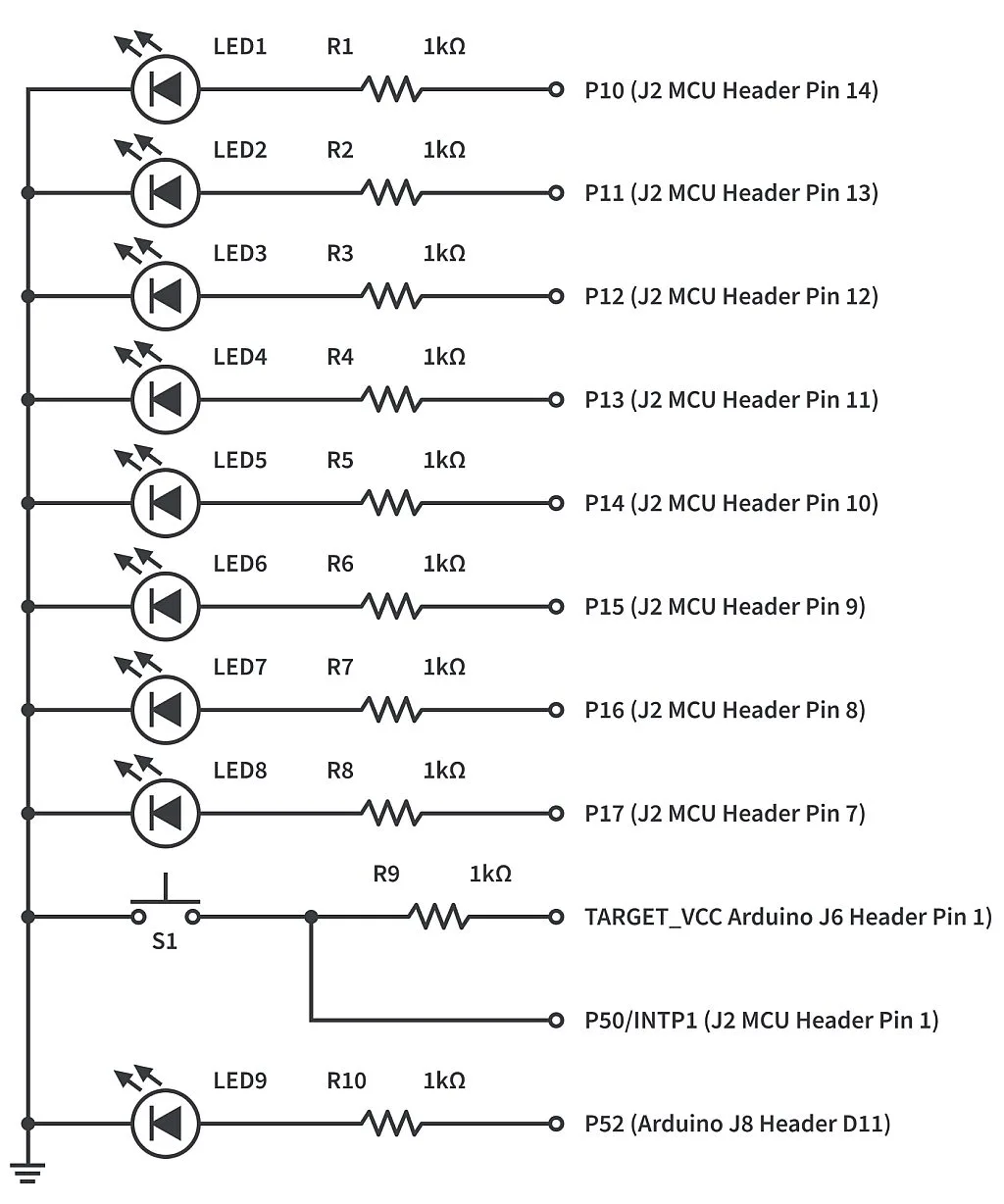
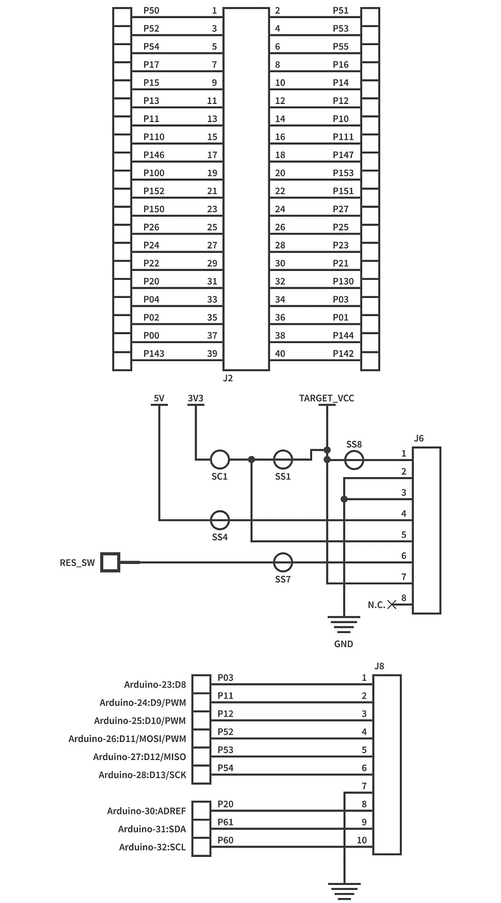
Here we have nine LEDs which represent the nine tasks mentioned in the Polling vs Interrupt example. LED1 to LED8 are connected to Port 1 pins while LED9 is connected to pin P52. Port 1 pins are connected to the MCU header J2. So if you haven’t yet mounted the MCU headers, this is the time to mount them or you can use other pins in the Arduino headers and just change the code. The external interrupt INTP1 is an alternate function of the GPIO P50 (check chapter 2.1.17 of the hardware user’s manual). So as you can see in the schematic diagram, we connected the pin P50 between the switch S1 and the 10k external pull-up resistor R9. Please check the RL78/G14 FPB schematic diagram to verify which headers Port 1 pins, pin P52, and pin P50 are connected.
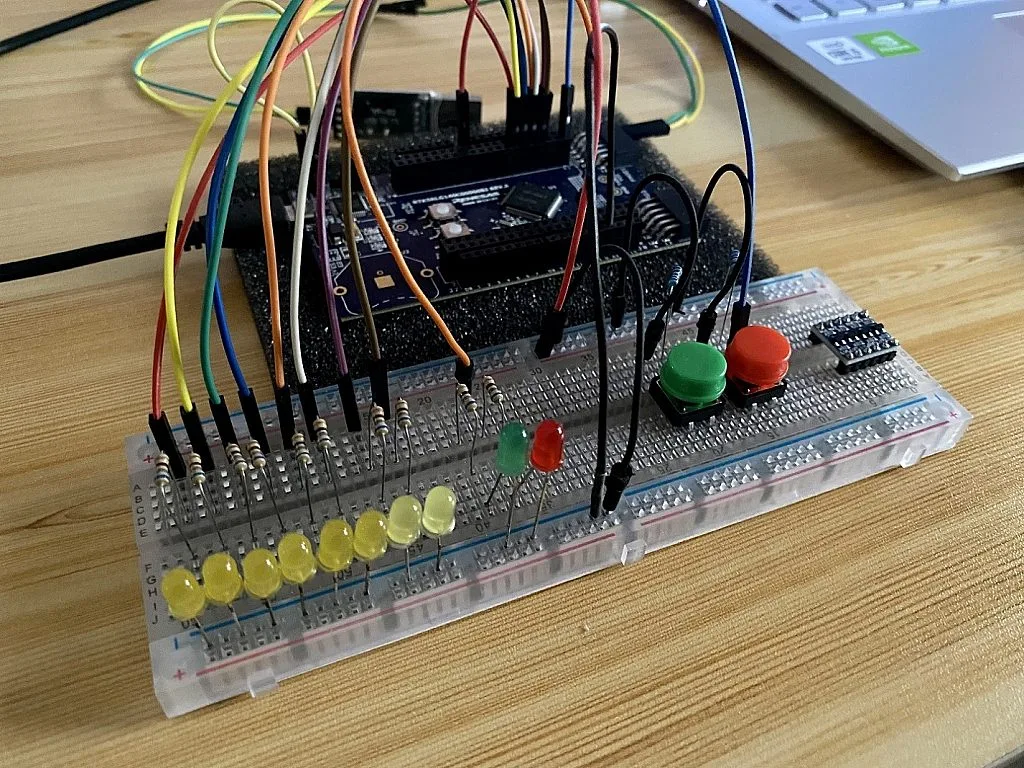
The flow of our program here is very simple. The normal operation is “turn on LED1 to LED8 and then turn them off from LED8 to LED1”. Each time an interrupt event occurs when we press switch S1, the normal operation is interrupted and then LED9 will be toggled. But before we demonstrate interrupts, we will try the blocking and non-blocking mode polling first. Let’s first create a project and then replace everything in the r_main.c file with the blocking mode polling code below. In case you forgot how to create a project, check this tutorial again: Renesas RL78 - 3. First Project.
/***********************************************************************************************************************
* DISCLAIMER
* This software is supplied by Renesas Electronics Corporation and is only intended for use with Renesas products.
* No other uses are authorized. This software is owned by Renesas Electronics Corporation and is protected under all
* applicable laws, including copyright laws.
* THIS SOFTWARE IS PROVIDED "AS IS" AND RENESAS MAKES NO WARRANTIES REGARDING THIS SOFTWARE, WHETHER EXPRESS, IMPLIED
* OR STATUTORY, INCLUDING BUT NOT LIMITED TO WARRANTIES OF MERCHANTABILITY, FITNESS FOR A PARTICULAR PURPOSE AND
* NON-INFRINGEMENT.  ALL SUCH WARRANTIES ARE EXPRESSLY DISCLAIMED.TO THE MAXIMUM EXTENT PERMITTED NOT PROHIBITED BY
* LAW, NEITHER RENESAS ELECTRONICS CORPORATION NOR ANY OF ITS AFFILIATED COMPANIES SHALL BE LIABLE FOR ANY DIRECT,
* INDIRECT, SPECIAL, INCIDENTAL OR CONSEQUENTIAL DAMAGES FOR ANY REASON RELATED TO THIS SOFTWARE, EVEN IF RENESAS OR
* ITS AFFILIATES HAVE BEEN ADVISED OF THE POSSIBILITY OF SUCH DAMAGES.
* Renesas reserves the right, without notice, to make changes to this software and to discontinue the availability
* of this software. By using this software, you agree to the additional terms and conditions found by accessing the
* following link:
* http://www.renesas.com/disclai...
*
* Copyright (C) 2011, 2021 Renesas Electronics Corporation. All rights reserved.
***********************************************************************************************************************/

/***********************************************************************************************************************
* File Name    : r_main.c
* Version      : CodeGenerator for RL78/G14 V2.05.06.02 [08 Nov 2021]
* Device(s)    : R5F104ML
* Tool-Chain   : GCCRL78
* Description  : This file implements main function.
* Creation Date: 31/08/2022
***********************************************************************************************************************/

/***********************************************************************************************************************
Includes
***********************************************************************************************************************/
#include "r_cg_macrodriver.h"
#include "r_cg_cgc.h"
/* Start user code for include. Do not edit comment generated here */
/* End user code. Do not edit comment generated here */
#include "r_cg_userdefine.h"

/***********************************************************************************************************************
Global variables and functions
***********************************************************************************************************************/
/* Start user code for global. Do not edit comment generated here */
void forloop_delay(void);
/* End user code. Do not edit comment generated here */
void R_MAIN_UserInit(void);

/***********************************************************************************************************************
* Function Name: main
* Description  : This function implements main function.
* Arguments    : None
* Return Value : None
***********************************************************************************************************************/
void main(void)
{
    R_MAIN_UserInit();
    /* Start user code. Do not edit comment generated here */
    PM1 = 0;
	P1 = 0;

	PM5_bit.no2 = 0;
	P5_bit.no2 = 0;

	PMK1 = 1U;    /* disable INTP1 operation */
	PIF1 = 0U;    /* clear INTP1 interrupt flag */
	PM5_bit.no0 = 1;	/* Set P50 as Input */
	EGN0_bit.no1 = 1U;	/* Falling Edge */

    while (1U)
    {
    	P1_bit.no0 = 1;
		forloop_delay();
		P1_bit.no1 = 1;
		forloop_delay();
		P1_bit.no2 = 1;
		forloop_delay();
		P1_bit.no3 = 1;
		forloop_delay();

		while (PIF1 != 1){}
		forloop_delay();
		forloop_delay();
		P5_bit.no2 = !P5_bit.no2;
		PIF1 = 0U;

		P1_bit.no4 = 1;
		forloop_delay();
		P1_bit.no5 = 1;
		forloop_delay();
		P1_bit.no6 = 1;
		forloop_delay();
		P1_bit.no7 = 1;
		forloop_delay();

		P1_bit.no7 = 0;
		forloop_delay();
		P1_bit.no6 = 0;
		forloop_delay();
		P1_bit.no5 = 0;
		forloop_delay();
		P1_bit.no4 = 0;
		forloop_delay();

		while (PIF1 != 1){}
		forloop_delay();
		forloop_delay();
		P5_bit.no2 = !P5_bit.no2;
		PIF1 = 0U;

		P1_bit.no3 = 0;
		forloop_delay();
		P1_bit.no2 = 0;
		forloop_delay();
		P1_bit.no1 = 0;
		forloop_delay();
		P1_bit.no0 = 0;
		forloop_delay();
    }
    /* End user code. Do not edit comment generated here */
}


/***********************************************************************************************************************
* Function Name: R_MAIN_UserInit
* Description  : This function adds user code before implementing main function.
* Arguments    : None
* Return Value : None
***********************************************************************************************************************/
void R_MAIN_UserInit(void)
{
    /* Start user code. Do not edit comment generated here */
    EI();
    /* End user code. Do not edit comment generated here */
}

/* Start user code for adding. Do not edit comment generated here */
void forloop_delay(void)
{
	uint16_t forloop_delay_var1;
	uint8_t forloop_delay_var2;

	for (forloop_delay_var1 = 0; forloop_delay_var1 < 65535; forloop_delay_var1++)
	{
		for (forloop_delay_var2 = 0; forloop_delay_var2 < 4; forloop_delay_var2++){}
	}
}
/* End user code. Do not edit comment generated here */
In line 42 we declared the forloop_delay() function and defined it in line 135 to line 144. We’re going to call this function to generate a software delay.
Inside the main() function line 52 to line 118, we call the R_MAIN_UserInit() function in line 54 which is defined in line 127 to line 132 to enable interrupts globally using the EI() function line 130.
In line 56 to line 60, we set all of the pins of Port 1 and pin P52 as outputs. As you can see, we used the macro name PM1 and P1 to use an 8-bit memory manipulation instruction which sets the entire register.
In line 62, we masked the INTP1 interrupt by writing 1 to its interrupt mask flag PMK1. You can check table 21-5 to table 21-8 of the RL78/G14 hardware user’s manual to see the interrupt mask flag of INTP1 and other interrupt sources. Table 21-5 to table 21-8 also shows which register the interrupt mask flag belongs to. PMK1 is bit no. 3 of the MK0L register (check figure 21-5 of the RL78/G14 hardware user’s manual). So writing 1 to MK0L_bit.no3 will mask INTP1. But we can just directly write 1 to PMK1 since inside the iodefine.h header file, the value of the macro name PMK1 is MK0L_bit.no3 — #define PMK1 MK0L_bit.no3.
In line 63, we cleared INTP1 interrupt flag PIF1. The interrupt flag of an interrupt source and the register it belongs to are also shown in table 21-5 to table 21-8 of the RL78/G14 hardware user’s manual. The macro name PIF1 is also defined inside the iodefine.h header file.
The purpose of masking PMK1 and clearing PIF1 is to ensure that there will be no interrupt generated as we are setting the other registers that enables edge detection of the external interrupt INTP1. As you can see in line 64 and line 65, we set the pin P50 or INTP1 pin as input and then make it detect a falling edge by writing 1 to bit no.1 of the EGN0 register. As shown in figure 21-10 of the RL78/G14 hardware user’s manual, we need to write 0 to the EGPn bit and 1 to the EGNn bit to select the falling edge. n here is 1 as the external interrupt being used is INTP1. After reset, the value of EGP0_bit.no1 and EGN0_bit.no1 is 0. So in our code we only write 1 to EGN0_bit.no1 since EGP0_bit.no1 is 0 by default.
So that will enable the P50/INTP1 pin to detect a falling edge now. Since we’re using polling here, we don’t need to unmask the PMK1 flag. So our code now enters the infinite while loop in line 67 to line 116.
    while (1U)
    {
    	P1_bit.no0 = 1;
		forloop_delay();
		P1_bit.no1 = 1;
		forloop_delay();
		P1_bit.no2 = 1;
		forloop_delay();
		P1_bit.no3 = 1;
		forloop_delay();

		while (PIF1 != 1){}
		forloop_delay();
		forloop_delay();
		P5_bit.no2 = !P5_bit.no2;
		PIF1 = 0U;

		P1_bit.no4 = 1;
		forloop_delay();
		P1_bit.no5 = 1;
		forloop_delay();
		P1_bit.no6 = 1;
		forloop_delay();
		P1_bit.no7 = 1;
		forloop_delay();

		P1_bit.no7 = 0;
		forloop_delay();
		P1_bit.no6 = 0;
		forloop_delay();
		P1_bit.no5 = 0;
		forloop_delay();
		P1_bit.no4 = 0;
		forloop_delay();

		while (PIF1 != 1){}
		forloop_delay();
		forloop_delay();
		P5_bit.no2 = !P5_bit.no2;
		PIF1 = 0U;

		P1_bit.no3 = 0;
		forloop_delay();
		P1_bit.no2 = 0;
		forloop_delay();
		P1_bit.no1 = 0;
		forloop_delay();
		P1_bit.no0 = 0;
		forloop_delay();
    }
    /* End user code. Do not edit comment generated here */
As you can see, the code inside the while loop is mostly just composed of lines that turn ON and OFF the LEDs. But in line 78 and line 102, there’s a while loop that blocks the normal operation of the code. It polls the status of the PIF1 flag. While PIF1 is 0 (switch S1 is not pressed), the code is stuck in an infinite loop doing nothing. When the switch S1 is pressed (PIF1 flag is set), the program will exit the while loop, toggle LED9, clear the PIF1 flag, and then return to its normal operation again. Upload the code to your RL78/G14 FPB to see how it works in real life.
So as you can see, the disadvantage of blocking mode polling is that the CPU still needs to wait for the interrupt flag to be set before it executes the task and proceeds to the other tasks.
Now, let’s check the code below for the non-blocking mode polling example.
/***********************************************************************************************************************
* DISCLAIMER
* This software is supplied by Renesas Electronics Corporation and is only intended for use with Renesas products.
* No other uses are authorized. This software is owned by Renesas Electronics Corporation and is protected under all
* applicable laws, including copyright laws.
* THIS SOFTWARE IS PROVIDED "AS IS" AND RENESAS MAKES NO WARRANTIES REGARDING THIS SOFTWARE, WHETHER EXPRESS, IMPLIED
* OR STATUTORY, INCLUDING BUT NOT LIMITED TO WARRANTIES OF MERCHANTABILITY, FITNESS FOR A PARTICULAR PURPOSE AND
* NON-INFRINGEMENT.  ALL SUCH WARRANTIES ARE EXPRESSLY DISCLAIMED.TO THE MAXIMUM EXTENT PERMITTED NOT PROHIBITED BY
* LAW, NEITHER RENESAS ELECTRONICS CORPORATION NOR ANY OF ITS AFFILIATED COMPANIES SHALL BE LIABLE FOR ANY DIRECT,
* INDIRECT, SPECIAL, INCIDENTAL OR CONSEQUENTIAL DAMAGES FOR ANY REASON RELATED TO THIS SOFTWARE, EVEN IF RENESAS OR
* ITS AFFILIATES HAVE BEEN ADVISED OF THE POSSIBILITY OF SUCH DAMAGES.
* Renesas reserves the right, without notice, to make changes to this software and to discontinue the availability
* of this software. By using this software, you agree to the additional terms and conditions found by accessing the
* following link:
* http://www.renesas.com/disclai...
*
* Copyright (C) 2011, 2021 Renesas Electronics Corporation. All rights reserved.
***********************************************************************************************************************/

/***********************************************************************************************************************
* File Name    : r_main.c
* Version      : CodeGenerator for RL78/G14 V2.05.06.02 [08 Nov 2021]
* Device(s)    : R5F104ML
* Tool-Chain   : GCCRL78
* Description  : This file implements main function.
* Creation Date: 31/08/2022
***********************************************************************************************************************/

/***********************************************************************************************************************
Includes
***********************************************************************************************************************/
#include "r_cg_macrodriver.h"
#include "r_cg_cgc.h"
/* Start user code for include. Do not edit comment generated here */
/* End user code. Do not edit comment generated here */
#include "r_cg_userdefine.h"

/***********************************************************************************************************************
Global variables and functions
***********************************************************************************************************************/
/* Start user code for global. Do not edit comment generated here */
void forloop_delay(void);
/* End user code. Do not edit comment generated here */
void R_MAIN_UserInit(void);

/***********************************************************************************************************************
* Function Name: main
* Description  : This function implements main function.
* Arguments    : None
* Return Value : None
***********************************************************************************************************************/
void main(void)
{
    R_MAIN_UserInit();
    /* Start user code. Do not edit comment generated here */
    PM1 = 0;
	P1 = 0;

	PM5_bit.no2 = 0;
	P5_bit.no2 = 0;

	PMK1 = 1U;    /* disable INTP1 operation */
	PIF1 = 0U;    /* clear INTP1 interrupt flag */
	PM5_bit.no0 = 1;	/* Set P50 as Input */
	EGN0_bit.no1 = 1U;	/* Falling Edge */

	while (1U)
	{
		P1_bit.no0 = 1;
		forloop_delay();
		P1_bit.no1 = 1;
		forloop_delay();
		P1_bit.no2 = 1;
		forloop_delay();
		P1_bit.no3 = 1;
		forloop_delay();

		if (PIF1 == 1)
		{
			forloop_delay();
			forloop_delay();
			P5_bit.no2 = !P5_bit.no2;
			PIF1 = 0U;
		}

		P1_bit.no4 = 1;
		forloop_delay();
		P1_bit.no5 = 1;
		forloop_delay();
		P1_bit.no6 = 1;
		forloop_delay();
		P1_bit.no7 = 1;
		forloop_delay();

		P1_bit.no7 = 0;
		forloop_delay();
		P1_bit.no6 = 0;
		forloop_delay();
		P1_bit.no5 = 0;
		forloop_delay();
		P1_bit.no4 = 0;
		forloop_delay();
		P1_bit.no3 = 0;
		forloop_delay();
		P1_bit.no2 = 0;
		forloop_delay();
		P1_bit.no1 = 0;
		forloop_delay();
		P1_bit.no0 = 0;
		forloop_delay();
	}
    /* End user code. Do not edit comment generated here */
}


/***********************************************************************************************************************
* Function Name: R_MAIN_UserInit
* Description  : This function adds user code before implementing main function.
* Arguments    : None
* Return Value : None
***********************************************************************************************************************/
void R_MAIN_UserInit(void)
{
    /* Start user code. Do not edit comment generated here */
    EI();
    /* End user code. Do not edit comment generated here */
}

/* Start user code for adding. Do not edit comment generated here */
void forloop_delay(void)
{
	uint16_t forloop_delay_var1;
	uint8_t forloop_delay_var2;

	for (forloop_delay_var1 = 0; forloop_delay_var1 < 65535; forloop_delay_var1++)
	{
		for (forloop_delay_var2 = 0; forloop_delay_var2 < 4; forloop_delay_var2++){}
	}
}
/* End user code. Do not edit comment generated here */
Actually, the code is just similar to the blocking mode polling code except that we use an if statement instead of a while loop. Also, we only used one if statement so that in real life, the disadvantage of the non-blocking mode polling will be noticeable.
Inside the while loop line 67 to line 111, the code will just repeatedly turn on LED1 to LED8 and then turn off LED8 to LED1. The code in line 78 to line 84 will not block the operation. This is the advantage of non-blocking mode polling over the blocking mode polling as the operation of the program will not be blocked. Upload the code to your RL78/G14 FPB to see how it works in reality.
However, If we want to execute the code inside the if statement so we press the switch S1 to set the PIF1 flag but the code is now in line 86 turning on LED5, we still need to wait for the program to finish the loop and execute line 69 to line 76 again before the code inside the if statement will be executed. If the code inside the if statement needs to be executed as soon as possible, then using a non-blocking mode polling is not a good idea.
Now, let’s check the code that uses interrupt to see how interrupts overcome the limitations of polling.
/***********************************************************************************************************************
* DISCLAIMER
* This software is supplied by Renesas Electronics Corporation and is only intended for use with Renesas products.
* No other uses are authorized. This software is owned by Renesas Electronics Corporation and is protected under all
* applicable laws, including copyright laws.
* THIS SOFTWARE IS PROVIDED "AS IS" AND RENESAS MAKES NO WARRANTIES REGARDING THIS SOFTWARE, WHETHER EXPRESS, IMPLIED
* OR STATUTORY, INCLUDING BUT NOT LIMITED TO WARRANTIES OF MERCHANTABILITY, FITNESS FOR A PARTICULAR PURPOSE AND
* NON-INFRINGEMENT.  ALL SUCH WARRANTIES ARE EXPRESSLY DISCLAIMED.TO THE MAXIMUM EXTENT PERMITTED NOT PROHIBITED BY
* LAW, NEITHER RENESAS ELECTRONICS CORPORATION NOR ANY OF ITS AFFILIATED COMPANIES SHALL BE LIABLE FOR ANY DIRECT,
* INDIRECT, SPECIAL, INCIDENTAL OR CONSEQUENTIAL DAMAGES FOR ANY REASON RELATED TO THIS SOFTWARE, EVEN IF RENESAS OR
* ITS AFFILIATES HAVE BEEN ADVISED OF THE POSSIBILITY OF SUCH DAMAGES.
* Renesas reserves the right, without notice, to make changes to this software and to discontinue the availability
* of this software. By using this software, you agree to the additional terms and conditions found by accessing the
* following link:
* http://www.renesas.com/disclai...
*
* Copyright (C) 2011, 2021 Renesas Electronics Corporation. All rights reserved.
***********************************************************************************************************************/

/***********************************************************************************************************************
* File Name    : r_main.c
* Version      : CodeGenerator for RL78/G14 V2.05.06.02 [08 Nov 2021]
* Device(s)    : R5F104ML
* Tool-Chain   : GCCRL78
* Description  : This file implements main function.
* Creation Date: 31/08/2022
***********************************************************************************************************************/

/***********************************************************************************************************************
Includes
***********************************************************************************************************************/
#include "r_cg_macrodriver.h"
#include "r_cg_cgc.h"
/* Start user code for include. Do not edit comment generated here */
/* End user code. Do not edit comment generated here */
#include "r_cg_userdefine.h"

/***********************************************************************************************************************
Global variables and functions
***********************************************************************************************************************/
/* Start user code for global. Do not edit comment generated here */
void forloop_delay(void);
void INTP1_Init(void);
void INTP1_Start(void);
void INTP1_Stop(void);
void INTP1_ISR(void);
/* End user code. Do not edit comment generated here */
void R_MAIN_UserInit(void);

/***********************************************************************************************************************
* Function Name: main
* Description  : This function implements main function.
* Arguments    : None
* Return Value : None
***********************************************************************************************************************/
void main(void)
{
    R_MAIN_UserInit();
    /* Start user code. Do not edit comment generated here */
    PM1 = 0;
	P1 = 0;

	PM5_bit.no2 = 0;
	P5_bit.no2 = 0;

    while (1U)
    {
    	P1_bit.no0 = 1;
		forloop_delay();
		P1_bit.no1 = 1;
		forloop_delay();
		P1_bit.no2 = 1;
		forloop_delay();
		P1_bit.no3 = 1;
		forloop_delay();
		P1_bit.no4 = 1;
		forloop_delay();
		P1_bit.no5 = 1;
		forloop_delay();
		P1_bit.no6 = 1;
		forloop_delay();
		P1_bit.no7 = 1;
		forloop_delay();

		P1_bit.no7 = 0;
		forloop_delay();
		P1_bit.no6 = 0;
		forloop_delay();
		P1_bit.no5 = 0;
		forloop_delay();
		P1_bit.no4 = 0;
		forloop_delay();
		P1_bit.no3 = 0;
		forloop_delay();
		P1_bit.no2 = 0;
		forloop_delay();
		P1_bit.no1 = 0;
		forloop_delay();
		P1_bit.no0 = 0;
		forloop_delay();
    }
    /* End user code. Do not edit comment generated here */
}


/***********************************************************************************************************************
* Function Name: R_MAIN_UserInit
* Description  : This function adds user code before implementing main function.
* Arguments    : None
* Return Value : None
***********************************************************************************************************************/
void R_MAIN_UserInit(void)
{
    /* Start user code. Do not edit comment generated here */
    EI();
    INTP1_Init();
    INTP1_Start();
    /* End user code. Do not edit comment generated here */
}

/* Start user code for adding. Do not edit comment generated here */
void forloop_delay(void)
{
	uint16_t forloop_delay_var1;
	uint8_t forloop_delay_var2;

	for (forloop_delay_var1 = 0; forloop_delay_var1 < 65535; forloop_delay_var1++)
	{
		for (forloop_delay_var2 = 0; forloop_delay_var2 < 4; forloop_delay_var2++){}
	}
}

void INTP1_Init(void)
{
    PMK1 = 1U;    /* disable INTP1 operation */
    PIF1 = 0U;    /* clear INTP1 interrupt flag */

    /* Set INTP1 high priority */
    PPR11 = 0U;
    PPR01 = 0U;

    PM5_bit.no0 = 1;	/* Set P50 as Input */
    EGN0_bit.no1 = 1U;	/* Falling Edge */
}

void INTP1_Start(void)
{
    PIF1 = 0U;    /* clear INTP0 interrupt flag */
    PMK1 = 0U;    /* enable INTP0 interrupt */
}

void INTP1_Stop(void)
{
    PMK1 = 1U;    /* disable INTP0 interrupt */
    PIF1 = 0U;    /* clear INTP0 interrupt flag */
}

void INTP1_ISR(void)
{
	INTP1_Stop();
	P5_bit.no2 = !P5_bit.no2;
	forloop_delay();
	forloop_delay();
	INTP1_Start();
}
/* End user code. Do not edit comment generated here */
As you can see in the code, we’ve declared four new functions in line 43 to line 46: INTP1_Init(), INTP1_Start(), INTP1_Stop(), and INTP1_ISR(). These functions are defined in line 133 to line 165.
When the program enters the main() function after hardware initialization, the first thing it executes is the R_MAIN_UserInit() function which is in line 112 to line 119. Then inside the R_MAIN_UserInit() function, three functions will be called, EI(), INTP1_Init(), and INTP1_Start().

As discussed earlier, to enable maskable interrupts, we need to set the IE flag and we can do that by calling the EI() function.
The INTP1_Init() function initializes the INTP1 interrupt. As shown in figure 5, to use an external interrupt, we need to configure these flags/bits: IE, IF, MK, PR0 and PR1, ISP0 and ISP1, and EGP and EGN. We’ve already discussed how to set or clear the INTP1 IF flag PIF1, MK flag PMK1, and its detection enable bits EGP1 and EGN1 and we’ve just mentioned that the IE flag is set by calling EI(). So this time, we just need to discuss the PR1, PR0 and ISP1, ISP0 flags. Table 21-5 to table 21-8 of the RL78/G14 hardware user’s manual shows the priority specification flags of INTP1 and other interrupt sources. For the configuration of the in-service priority flags, refer to the table below.
| ISP1 | ISP0 | Priority of interrupt currently being serviced |
| 0 | 0 | Enables interrupt of level 0 (while interrupt of level 1 or 0 is being serviced) |
| 0 | 1 | Enables interrupt of level 0 and 1 (while interrupt of level 2 is being serviced) |
| 1 | 0 | Enables interrupt of level 0 to 2 (while interrupt of level 3 is being serviced) |
| 1 | 1 | Enables all interrupts (waits for acknowledgment of an interrupt) |
void INTP1_Init(void)
{
    PMK1 = 1U;    /* disable INTP1 operation */
    PIF1 = 0U;    /* clear INTP1 interrupt flag */

    /* Set INTP1 high priority */
    PPR11 = 0U;
    PPR01 = 0U;

    PM5_bit.no0 = 1;	/* Set P50 as Input */
    EGN0_bit.no1 = 1U;	/* Falling Edge */
}
In line 135 to line 136, we masked the INTP1 PMK1 flag and cleared its PIF1 flag first to make sure that INTP1 would not generate an interrupt. In this example, we set the priority of the INTP1 interrupt to high and we did that by writing 0 to its PR1 flag PPR11 and PR0 PPR01 flag (check table below for the configuration of priority level). As you can see in line 139 and line 140, we set both PPR11 and PPR01 to 0. Inside iodefine.h header file, the value of the macro name PPR11 is PR10L_bit.no3 — #define PPR11 PR10L_bit.no3 and PPR01 is PR00L_bit.no3 — #define PPR01 PR00L_bit.no3.
| XXPR1X | XXPR0X | Priority level selection |
| 0 | 0 | Specify level 0 (high priority level) |
| 0 | 1 | Specify level 1 |
| 1 | 0 | Specify level 2 |
| 1 | 1 | Specify level 3 (low priority level) |
In this example, we don’t need to filter interrupts according to their priority level so we’ll just enable all interrupts by setting ISP1, ISP0 bits to 11. According to chapter 21.3.5 of the RL78/G14 hardware user’s manual, after reset, the value of the PSW register is 06H (hex). That means that we don’t need to touch the ISP1, ISP0 bits anymore as their value is already 1 by default. As you can see in our code, we didn’t set these bits anymore.
void INTP1_Init(void)
{
    PMK1 = 1U;    /* disable INTP1 operation */
    PIF1 = 0U;    /* clear INTP1 interrupt flag */

    /* Set INTP1 high priority */
    PPR11 = 0U;
    PPR01 = 0U;

    PM5_bit.no0 = 1;	/* Set P50 as Input */
    EGN0_bit.no1 = 1U;	/* Falling Edge */
}
Now, to enable edge detection at P50/INTP1 pin, we set it as input in line 142 and in line 143, we set it to detect a falling edge. So that’s the end of the INTP1_Init() function and the program returns to the R_MAIN_UserInit() function and calls the INTP1_Start().
void INTP1_Start(void)
{
    PIF1 = 0U;    /* clear INTP0 interrupt flag */
    PMK1 = 0U;    /* enable INTP0 interrupt */
}
INTP1_Start() is in line 146 to line 150. The purpose of this function is just to enable INTP1 by clearing first the PIF1 interrupt flag line 148 and then unmasking the PMK1 flag line 149. After this, the function returns again to the R_MAIN_UserInit() function then back to line 60 of the main() function. But before that, let’s first discuss the INTP1_Stop() and the INTP1_ISR() functions.
The INTP1_Stop() function will just mask the PMK1 flag and clear the PIF1 flag. We will call this function each time the program jumps to the INTP1 ISR.
void INTP1_Stop(void)
{
    PMK1 = 1U;    /* disable INTP0 interrupt */
    PIF1 = 0U;    /* clear INTP0 interrupt flag */
}

void INTP1_ISR(void)
{
	INTP1_Stop();
	P5_bit.no2 = !P5_bit.no2;
	forloop_delay();
	forloop_delay();
	INTP1_Start();
}
/* End user code. Do not edit comment generated here */
The INTP1_ISR() function which is in line 158 to line 165 is where the program jumps each time the INTP1 interrupt is generated (PIF1 flag is set to 1). Inside it, as you can see we called the INTP1_Stop() function line 160 to clear the PIF1 flag and mask the INTP1 interrupt. Then we toggle pin P52 line 161 which will turn ON or turn OFF LED9. The purpose of the delay in line 162 and line 163 is just for us to see that the normal operation of the MCU is really interrupted. These delays are just for demo. Good practice is to make the execution time of an ISR as short as possible so that if another interrupt occurs, the CPU will not miss it while already inside an ISR. There are ways in RL78 MCUs to manage multiple interrupts occurring at the same time but we will not discuss it in this tutorial.
In line 164, we clear the PIF1 flag and unmask the PMK1 flag by calling the INTP1_Start() function to enable the INTP1 interrupt again. The program will exit the INTP1_ISR() function and return to where it was interrupted.
So we’ve set the flags/bits related to the INTP1 interrupt and we’ve also created its ISR. However, we still need to do something so that our program will really jump to the ISR when INTP1 detects a falling edge. Actually, there’s an easy way to do this and that is to use the built-in Code Generator in e2 studio for RL78 MCUs. We can even easily generate codes that will configure the interrupt and create its ISR. However, I think we need to know how to do this manually so that later we can remove the unnecessary codes generated by the Code Generator and just use what’s needed.
I found online how to initialize RL78 interrupts using GCC for Renesas RL78 and found this thread in llvm-gcc-renesas.com forum: Interrupts Intialization (GCC for Renesas 4.9.2.201801-GNURL78 Linux Toolchain (ELF Format). Someone from the GNU Tools Team provided these instructions:
- The first step is we need to declare interrupt handlers by using attribute pragma. In the project explorer window, let’s open the header file
r_cg_interrupt_handlers.hunder thesrcfolder and declare the interrupt handler.
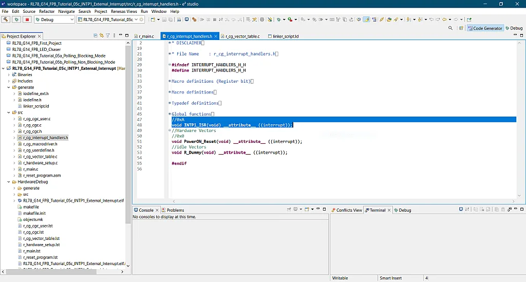
- We need to follow this follow this format:
void interrupt_prototype(void) __attribute__ ((interrupt));
Replaceinterrupt_prototypewith a valid function name that you want. In our case, we choseINTP1_ISR.
- The 2nd step is we need to declare the interrupt vector table, initialize it with interrupt handlers, and place it in a section.
const void *Vectors[] __attribute__ ((section (".vects"))) = { ..., interrupt_prototype, ... };
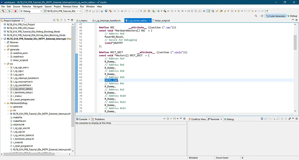
- Luckily the IDE and the code generator did this step for us when we created the project. All we need to do is identify the vector address of the
INTP1ISR and replace its dummy name as shown in figure 13. Table 21-1 to table 21-4 of the RL78/G14 hardware user’s manual shows the vector table address of the interrupt sources. The CPU actually uses this table to check which address it will jump to execute the ISR. The address ofINTP1is0xA.
- The final step is to place the reset vector and interrupt vector table at the right address starting from 0:
MEMORY
{
VEC : ORIGIN = 0x0, LENGTH = 4
IVEC : ORIGIN = 0x4, LENGTH = 188
...
}
SECTIONS
{
.vec 0x0: AT(0x0)
{
KEEP(*(.vec))
} > VEC
.vects 0x4: AT(0x4)
{
KEEP(*(.vects))
} > IVEC
...
}
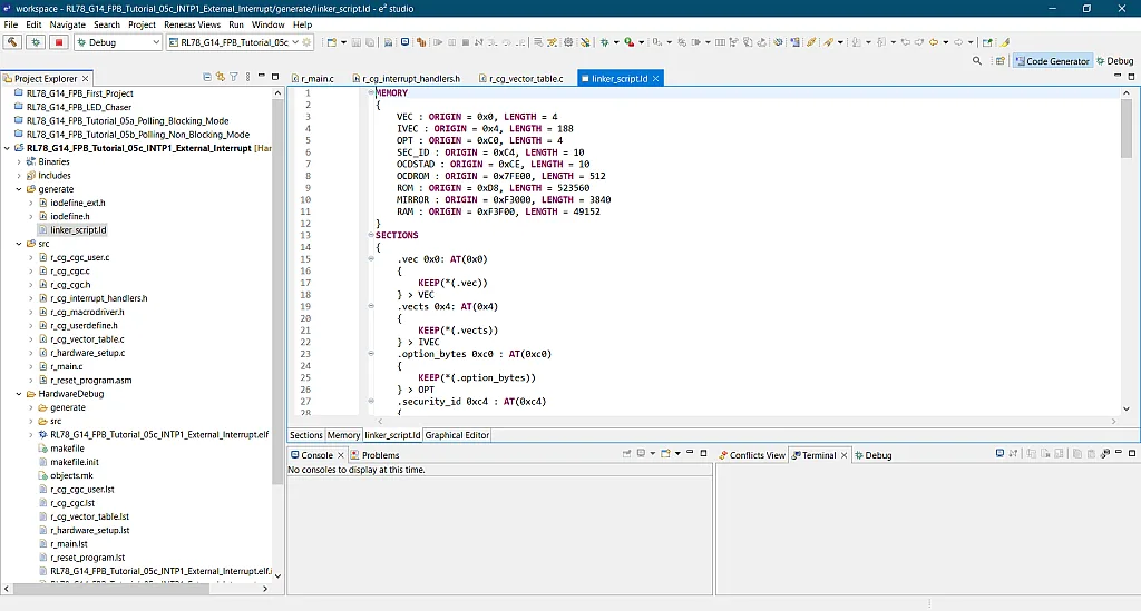
- But this was already configured when the project was created (see figure 14) so no need to do this step.
Finally we’re done initializing the interrupt. Now, let’s go back to the main function.
/***********************************************************************************************************************
* Function Name: main
* Description  : This function implements main function.
* Arguments    : None
* Return Value : None
***********************************************************************************************************************/
void main(void)
{
    R_MAIN_UserInit();
    /* Start user code. Do not edit comment generated here */
    PM1 = 0;
	P1 = 0;

	PM5_bit.no2 = 0;
	P5_bit.no2 = 0;

    while (1U)
    {
    	P1_bit.no0 = 1;
		forloop_delay();
		P1_bit.no1 = 1;
		forloop_delay();
		P1_bit.no2 = 1;
		forloop_delay();
		P1_bit.no3 = 1;
		forloop_delay();
		P1_bit.no4 = 1;
		forloop_delay();
		P1_bit.no5 = 1;
		forloop_delay();
		P1_bit.no6 = 1;
		forloop_delay();
		P1_bit.no7 = 1;
		forloop_delay();

		P1_bit.no7 = 0;
		forloop_delay();
		P1_bit.no6 = 0;
		forloop_delay();
		P1_bit.no5 = 0;
		forloop_delay();
		P1_bit.no4 = 0;
		forloop_delay();
		P1_bit.no3 = 0;
		forloop_delay();
		P1_bit.no2 = 0;
		forloop_delay();
		P1_bit.no1 = 0;
		forloop_delay();
		P1_bit.no0 = 0;
		forloop_delay();
    }
    /* End user code. Do not edit comment generated here */
}
In line 60 to line 64, we set Port 1 pins and pin P52 as outputs. Then inside the infinite while loop line 66 to line 101, all we can see are code lines that will turn on the LEDs from LED1 to LED8 and turn them off from LED8 to LED1. No polling method used. So there’s no way that LED9 will be toggled unless the program jumps to the INTP1 ISR.
So let’s upload the code to the RL78/G14 FPB and see how it works. As you can see, if we don’t press the switch, the normal operation of the MCU is turn on LED1 to LED8 and then turn off LED8 to LED1. Try pressing the switch and you’ll see the normal operation being interrupted. LED9 will be toggled and after that the MCU will go back to its normal operation.
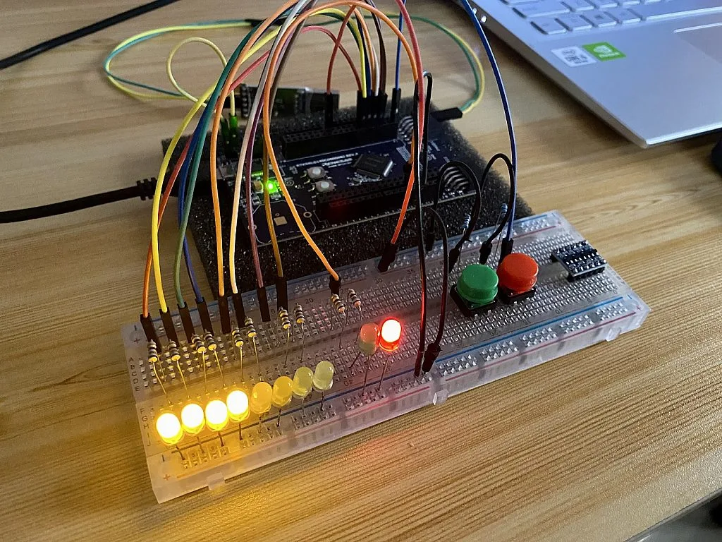
The advantage of this compared to polling is that the task of toggling LED9 is almost immediately executed. Also, we don’t need to put other tasks on hold just like in blocking mode polling or wait for the MCU to finish the other task to execute an important task just like in non-blocking mode polling.
So that’s all for now! I hope you enjoyed this tutorial. If you have questions, you can leave it in the comments section below or you can message us. See you next time!

Get the latest tools and tutorials, fresh from the toaster.


