UART - Universal Asynchronous Receiver Transmitter
Published
Digital systems are about sharing and storing information in the form of 1’s and 0’s. To share this information with multiple devices that have different architectures, we need a universal approach to data exchange. This is where various communication protocols come into action, one of which is the Universal Asynchronous Receiver Transmitter (UART). It is one of the most prominently used communication protocols in embedded electronics. It is a serial, full-duplex, asynchronous, and board-to-board communication protocol. Before understanding the protocol, let’s break down some major keywords.
- Serial communication: For serial communication, only one or two connections are required for sending or receiving the data. Data reception and transmission are done one bit at a time or sequentially.
- Parallel communication: For parallel communication, multiple lines are present for data exchange. The number of lines used for the transmission or reception of data is called the bus width of a device. In the below figure, you can determine that the bus width is 8 bits. All 8 bits are transferred at the same time.

- Asynchronous communication: In asynchronous communication, devices do not share a common clock to synchronize the data transfer. Instead, they agree upon an identical transfer rate and configure the device's internal clock to capture or transfer the data.
- Full Duplex communication: In a full-duplex type of communication, separate lines are present to simultaneously carry out transmission and reception.
From the figure below, you can see that the device sends and receives the data in parallel.

Now that we have the basic idea of some important terminologies, we can move ahead and understand how UART works.
UART Explained
As UART is a full duplex and asynchronous communication protocol, both transmission and reception of the data can occur at the same time. Hence we need separate pins for transferring and receiving the data. We have the TX pin for transmission and the RX pin for data reception. Transmitted data from the TX port of one device is received by the RX port of the other device and vice versa. Therefore the connections between the devices are made so that TX1 is connected to RX2, and TX2 is connected to RX1 for the communication to happen. The figure below explains how the connections for the UART protocol are done.
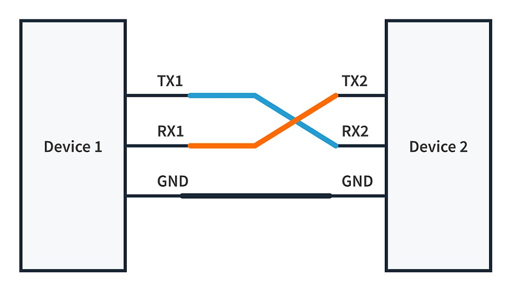
One of the most common mistakes while setting up the hardware of UART for the first time is connecting TX1 with TX2 and RX1 with RX2. This mistake can be hard to spot and get quite frustrating. So always make sure that you connect one device’s TX with another’s RX. Another important thing to note here is that the GND of the devices should also be connected. This is essential because electronic devices read or write data regarding voltage differences (5V or 3.3 V HIGH or 1 and 0V: LOW). To measure a voltage difference, we need a reference voltage. Connecting the ground provides that reference which prevents data corruption while communicating.
With the connections done, we meet an end to the hardware setup. Let’s move forward to understanding what a UART data packet is and what’s inside it:

1. Synchronization Bits
There is 1 start bit and 1 or 2 stop bits. They indicate the start and end of the packet. The line is pulled to 0 or LOW when the transfer is initiated, indicating the start of the frame, and pulled to 1 or HIGH again when the transfer is complete. When the line is 1 or HIGH, it is considered idle and signifies no data transfer in progress. There is only 1 bit to represent the "start", but stop bits are configurable to 1 or 2. For some microcontrollers, like the STM32F4xx series, the stop bits can also be configured to 1.5.

2. Data Bits
This part of the data frame is the heart of the matter as it carries the information to be sent to the receiver. The length of this chunk can vary from 5 to 9 bits, depending upon the agreed configuration between devices. The standard data size is 8 bits or 1 byte. As per the UART standards, the protocol follows little endianness, i.e., data is sent from LSB (Least Significant Bit) to MSB (Most Significant Bit), but it can also be configured to follow big endianness,i.e., from MSB to LSB.

3. Parity Bit
UART comes with an error-checking mechanism to check for the integrity of the received data chunk. As data is sent byte-by-byte in UART, error checking is done on each received byte. It uses a parity bit to do this; it is an error-checking code that is sent after the data bits. There are two modes for parity bit: odd or even.
Odd parity check: To check the integrity of the chunk, the program checks for the number of 1’s present in the data, including the parity bit. The transmitter performs the following steps to generate the parity bit for the data frame.
- Counts the number of 1’s in the data bits.
- If the number of 1’s is odd, then it sets the parity bit to 0, otherwise, it is set to 1. This process makes the total number of 1’s in the chunk(data bits + the parity bit) odd.
- The receiver checks whether the number of 1’s in the chunk received (including the parity bit) is odd or even. If there is an odd number of 1’s, the data is valid. If there are an even number of 1’s, it is invalid.
Even parity check: Instead of an odd number of 1’s in data, even parity checks for an even number of 1’s and follows the same methods on the transmitter and receiver side. The parity bit is set to 1 if there are odd numbers of 1’s and to 0 if there are even numbers of 1’s in the chunk. Ultimately the goal is to make the number of 1’s in the data transfer even. The receiver checks for the even number of 1’s in the chunk (data bits + parity bit) to validate the data transfer.
It is a simple error-checking mechanism and it fails if more than one bit is corrupted while transmitting. It also cannot identify which bit was corrupted during transmission.
Great! We have our data ready to be sent. But how does UART synchronize the data transfer without having any common clock? This is done by a configuration called “Baud Rate”.
4. Baud Rate
It specifies the speed of the data being sent in bps (bits-per-second). For the UART communication to take place, devices are set to identical baud rates. Some standard baud rates are 9600, 38400, 115200, 921600, etc. Invert the baud rate, and you'll have the time taken by each bit to get transferred. For example,
Hence, with the baud rate of 9600, each bit is transmitted in 104.16 microseconds. For the hardware, the line will be pulled up or down for 104.16 microseconds by the device.
Now you know almost everything required to implement the protocol. This knowledge is essential to debug the program in case of any strange behavior. Since we are done with the theory, let’s get to the implementation.
UART Implementation
For simplicity, we will use an Arduino UNO to communicate with the PC for printing "Hello World" on the serial monitor using UART communication. A computer doesn't have external ports for UART; instead, the communication is carried out with a USB to UART converter. But we don’t need to dive deep into that particular topic because the Arduino hardware and software already take care of that for us. Also, if you don’t have the required hardware to do this, feel free to use online simulators. (Wokwi, Tinkercad, are among the few). Let us begin...
Per the documentation of Arduino UNO, Serial0 is used for communication between the computer and ATmega328p (ATmega328p is the microcontroller on the Arduino UNO development board). Serial0 is also available as digital pins 0 and 1 on the Arduino UNO board. We won’t make any external connections to those pins because the communication with the PC takes place via the USB cable. But these pins can be used if we wish to communicate with another microcontroller.

First, we need to specify the baud rate to start the communication. We’ll use a baud rate of 9600 bps. By default, Arduino UNO uses an 8-N-1 data frame, i.e., 8 bits of data, no parity bit, and 1 stop bit. Below is the code required to perform the simple task of sending 'Hello world' to the PC.
void setup() {
   // the baud rate is set to 9600 bps
   Serial.begin(9600);
}
void loop() {
   // a string is transmitted over Serial0
   Serial.println("Hello World");
   // standby for 50 ms
   delay(50);
}
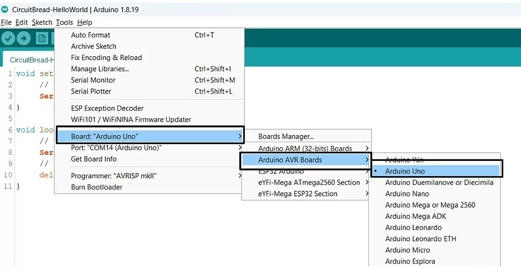
Simply add that code to the Arduino IDE, connect the board to your PC, and upload the code to your board after selecting the board and port from the Tools section of the IDE.
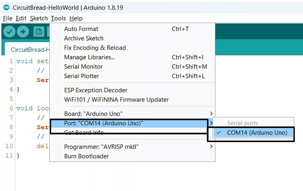
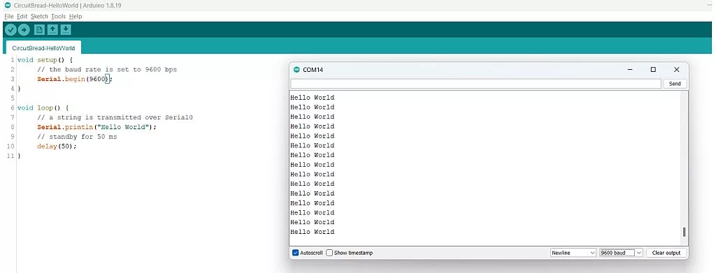

If you, too, can see “Hello World” on your screen, pat yourself on the back. If you don’t see it, don't worry; you can go back and try again. Keep up the excitement!
We'll go one step forward and understand how the whole text is transmitted to the Serial monitor. The text we see is “Hello World,” but on the backend, Arduino’s Serial.println function adds a special character ‘\n’ (new line) at the end of the text and converts the input text into ASCII. So the actual text transmitted is "Hello World\n” containing 12 ASCII characters. It is sent character by character. Hence it takes 12 data frames to transmit the whole text to the PC.
The first character sent is ‘H,’ with an ASCII value of ‘104’. The binary equivalent of ‘104’ is 01101000. This sequence of 0’s and 1’s is present in the data bits of the first data frame of UART. The ‘0’ before the data frame is the start bit, and the ‘1’ at the end is the stop bit.
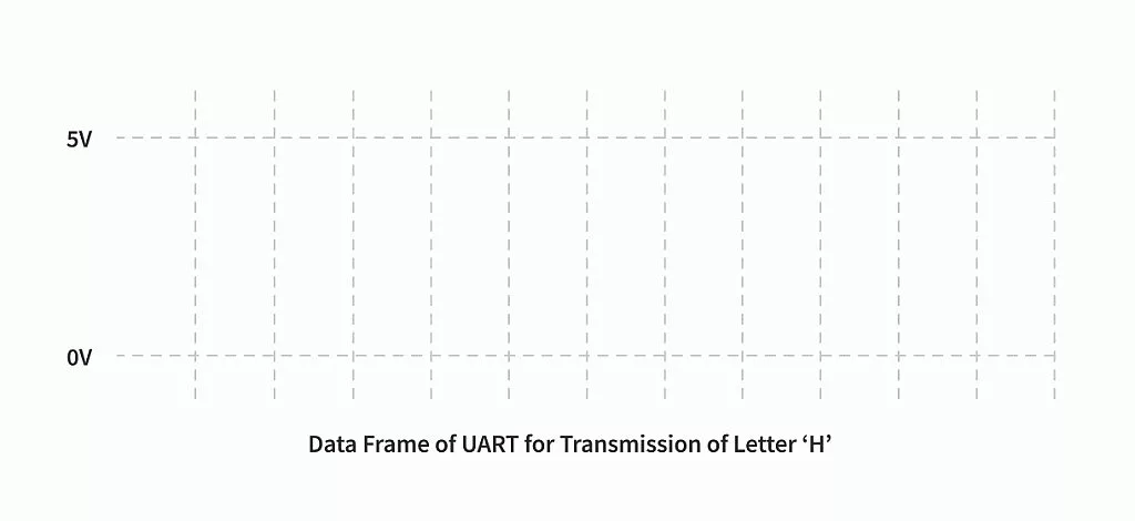
After the above packet representing ‘H’ gets sent, it is followed by the packet containing ‘e,’ and so on, until all the characters are transferred, one by one.
Now that we have a magnified look at what a data-stuffed UART frame looks like, let’s zoom out and look at the complete transfer. Here is a demonstration of how all the letters are transmitted.

We can see how each data frame transmitted one character, and the whole string was sent to the device one by one.
We hope that, by now, you can understand why UART is such a popular communication protocol. Its simplicity and ease of setup always make it the go-to communication protocol for sensors and devices. But this simplicity comes at a cost:
- It only supports communication between two devices. You can’t have multiple devices communicating over the same line.
- UART supports baud rates like 921000 (and even more!), but it is still comparatively slower than other protocols like SPI and I2C.
Even with these disadvantages, UART is still preferred by many companies that manufacture sensors and smart motor drivers to provide easy interfacing without having to worry about the architecture of the microcontroller used by the user. One such example is the TfMini, a LiDar distance sensor, which provides sensor readings for the distance measured in meters over UART. Serial interfaces in 3D printers have special packets that carry out specific tasks for debugging or installing a new component; likewise, we, too, can build complex tools and interfaces with a simple yet robust communication protocol like UART.

Get the latest tools and tutorials, fresh from the toaster.


