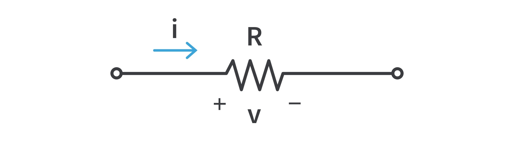
Ohm’s law states that the voltage v across a resistor is directly proportional to the current i flowing through the resistor: v ∝ i
The resistance R of an element denotes its ability to resist the flow of electric current; it is measured in ohms (Ω) in honor of Georg Simon Ohm (1787–1854), a German physicist whose work in electrical research resulted in his famous law.
Ohm defined the constant of proportionality for a resistor to be the resistance. Hence, v=iR which is the mathematical form of Ohm’s law.
v=iR ⇒ R=v/i; thus 1 Ω =1 V/A
The direction of current and the polarity of voltage must conform with the Passive sign convention: if the current flows from a higher potential to a lower potential, v=iR. If current flows from a lower potential to a higher potential, v=-iR.
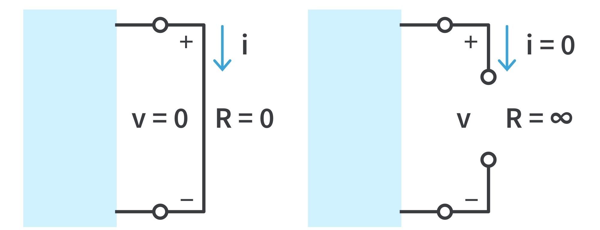
A short circuit is a circuit element with resistance approaching zero (v=iR =0; the voltage is zero, the current could be any value ).
An open circuit is a circuit element with resistance approaching infinity. (i=v/R→∞ =0; the current is zero, the voltage could be any value).
A short circuit (left) and an open circuit (right)
Not all resistors obey Ohm’s law. A resistor that obeys Ohm’s law is known as a linear resistor, with constant resistance.
Conductance is the ability of an element to conduct electric current, measured in mhos (℧) or siemens (S); it is the reciprocal of resistance, denoted by G: G=1/R=i/v.
Nodes, Branches, and Loops
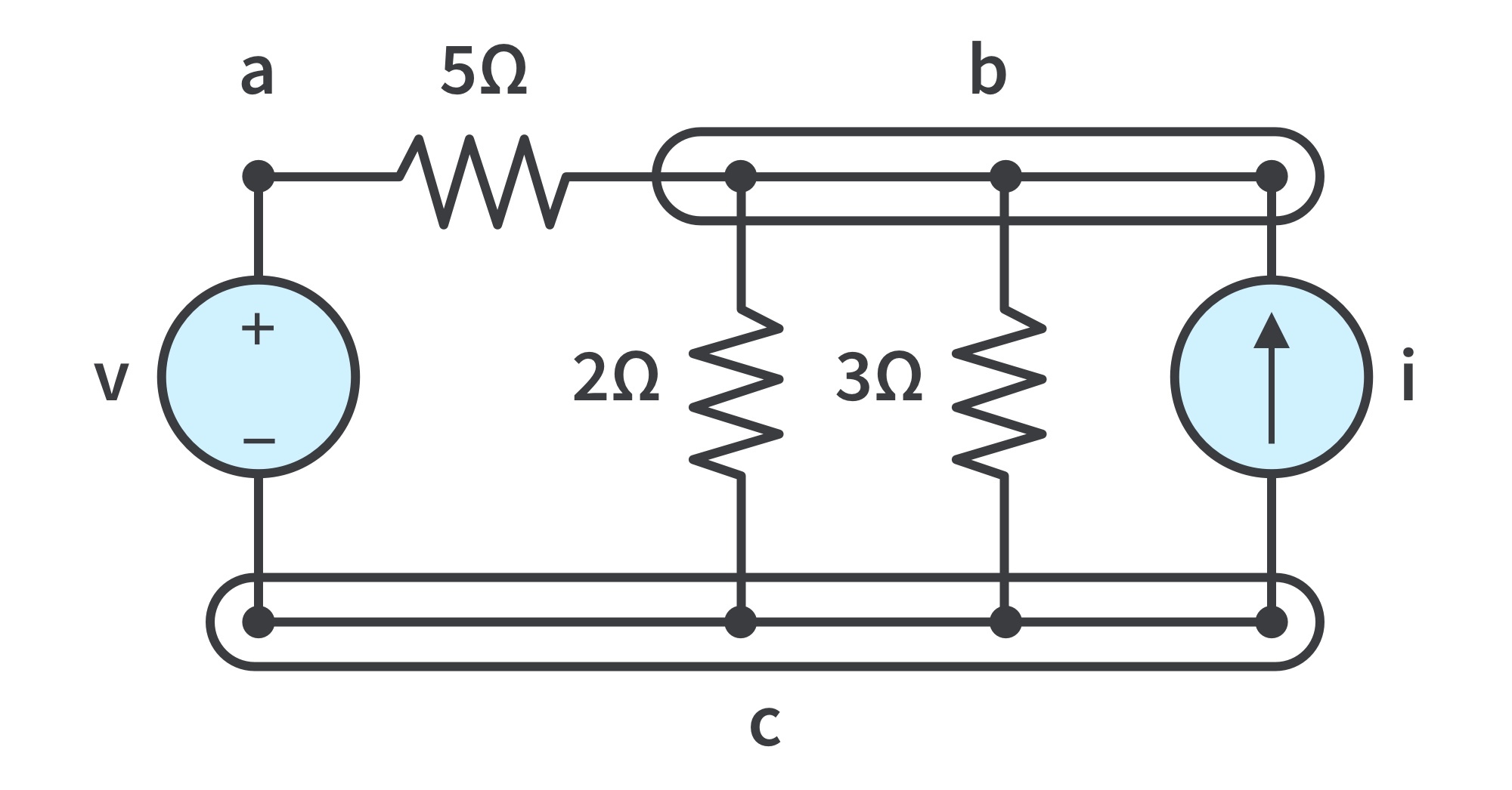
Circuit ABC
A branch represents any single two-terminal element such as a voltage source or a resistor.
The circuit in the figure has five branches, namely, the voltage source, the current source, and the three resistors.
A node is the point of connection between two or more branches; usually indicated by a dot in a circuit. If a wire (short circuit) connects two nodes, the nodes constitute a single node.
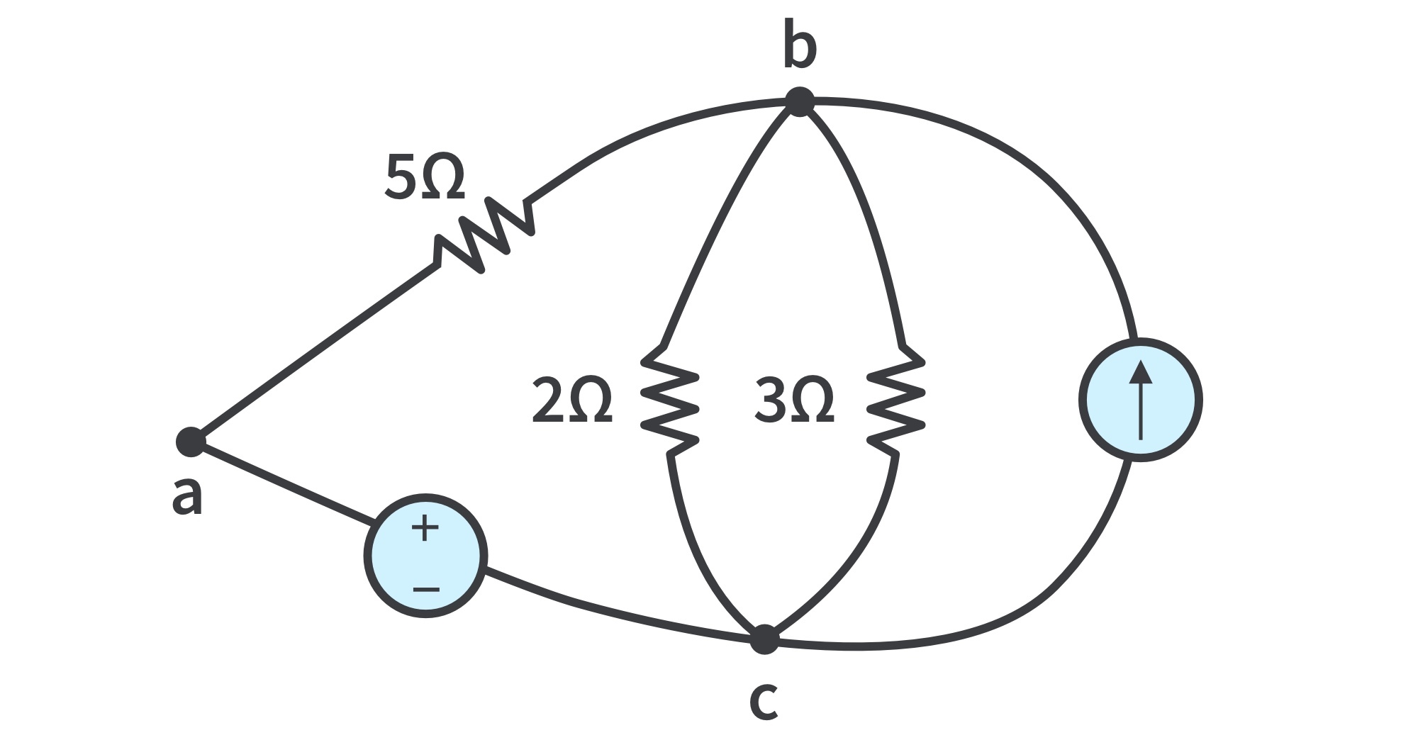
The circuit has three nodes a, b, and c. The three points forming node b are connected by perfectly conducting wires and therefore constitute a single point. The same is true of the four points forming node c. Redrawing the circuit demonstrates that it only has three nodes; the two circuits are identical:
Redrawn circuit ABC
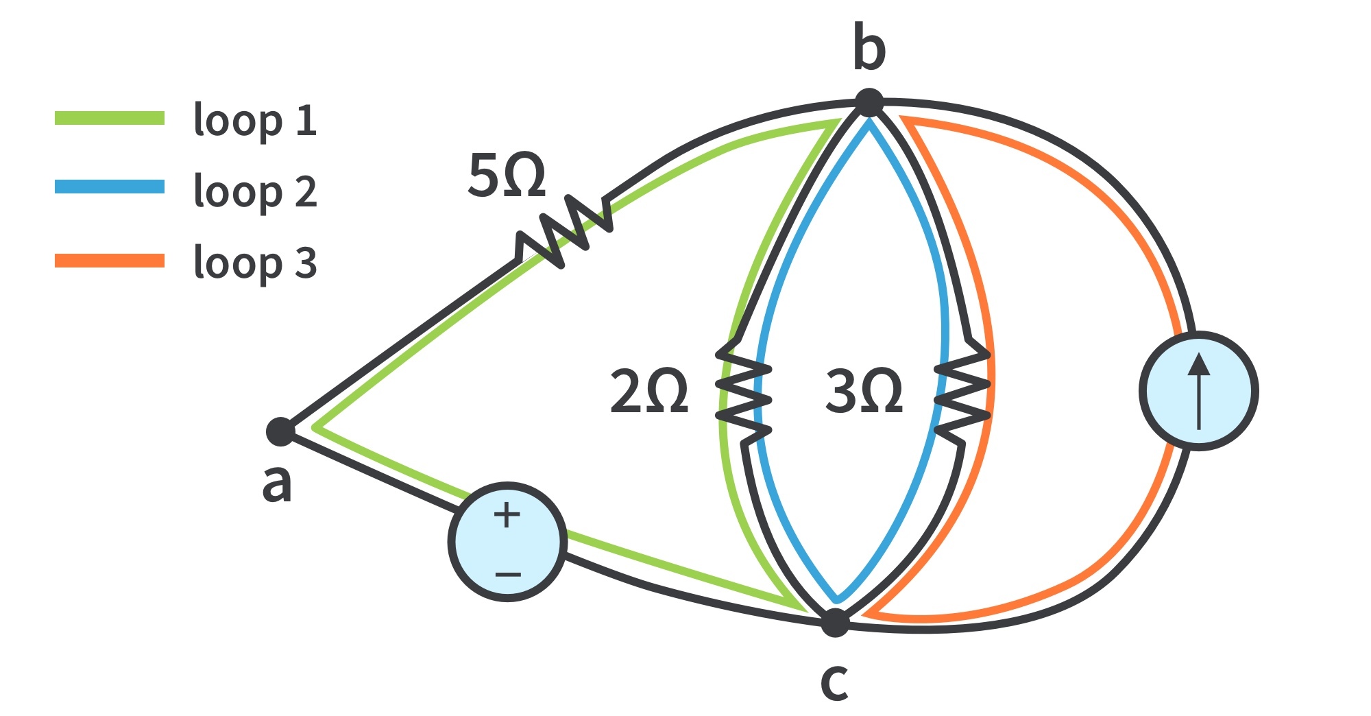
A loop is any closed path in a circuit; formed by starting at a node, passing through a set of nodes, and returning to the starting node without passing through any node more than once.
Independent loop: contains at least one branch which is not a part of another independent loop. Independent loops or paths result in independent sets of equations.
In the redrawn circuit, loop (1) abca with the 2Ω resistor is independent. A second loop (2) with the 3Ω resistor and the current source is independent. The third loop could be the one with the 2Ω resistor in parallel with the 3Ω resistor.
Redrawn circuit with loops
A network with b branches, n nodes, and l independent loops will satisfy the fundamental theorem of network topology: b=l+n-1
Two or more elements are in series if they exclusively share a single node and consequently carry the same current. For example, two elements are in series if they share one common node and no other element is connected to that common node.
Two or more elements are in parallel if they are connected to the same two nodes and consequently have the same voltage across them. Elements in parallel are connected to the same pair of terminals.
Elements may be connected in a way that they are neither in series nor in parallel.
In the circuit, the voltage source and the 5Ω resistor are in series. The 2-Ω resistor, the 3-Ω resistor, and the current source are in parallel. The 5-Ω and 2-Ω resistors are neither in series nor in parallel with each other.
Kirchhoff’s Laws
Kirchhoff’s current law (KCL)
states that the algebraic sum of currents entering a node (or a closed boundary) is zero; based on the law of conservation of charge.
Mathematically, KCL implies that . is the number of branches connected to the node, is the nth current entering (or leaving) the node.
Alternative form of KCL: the sum of the currents entering a node is equal to the sum of the currents leaving the node. Currents entering a node may be regarded as positive, currents leaving the node may be taken as negative or vice versa, as long as the direction is consistent.
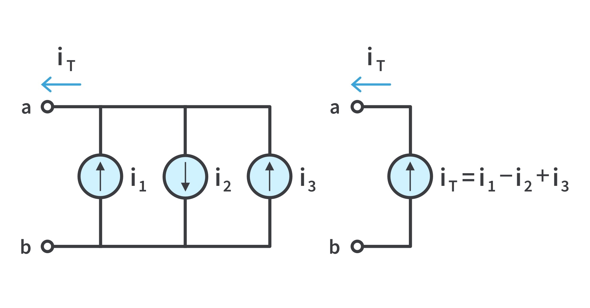
KCL can be applied to current sources in parallel: the combined current is the algebraic sum of the current supplied by individual sources
Current sources in parallel and the equivalent circuit
KCL holds as elements connected in series always have the same current passing through them. To avoid violating KCL, current sources are not allowed to be connected together in series.
Kirchhoff’s Laws
Kirchhoff’s voltage law (KVL)
states that the algebraic sum of all voltages around a closed path (or loop) is zero; based on the principle of conservation of energy.
Mathematically, KVL implies that. is the number of voltages in the loop (or branches in the loop), is the mth voltage.
KVL can be applied in two ways: by taking either a clockwise or a counterclockwise trip around the loop.
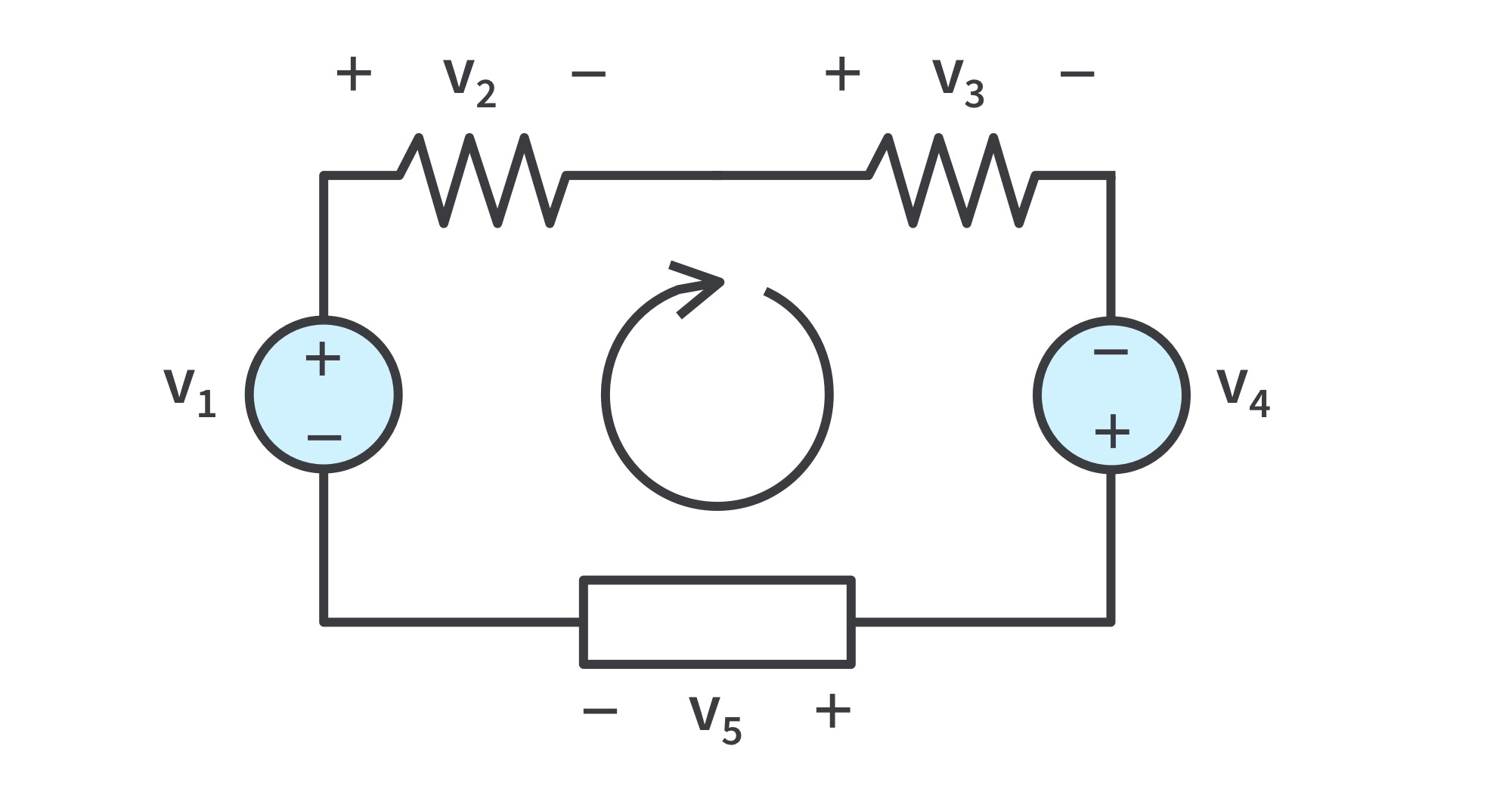
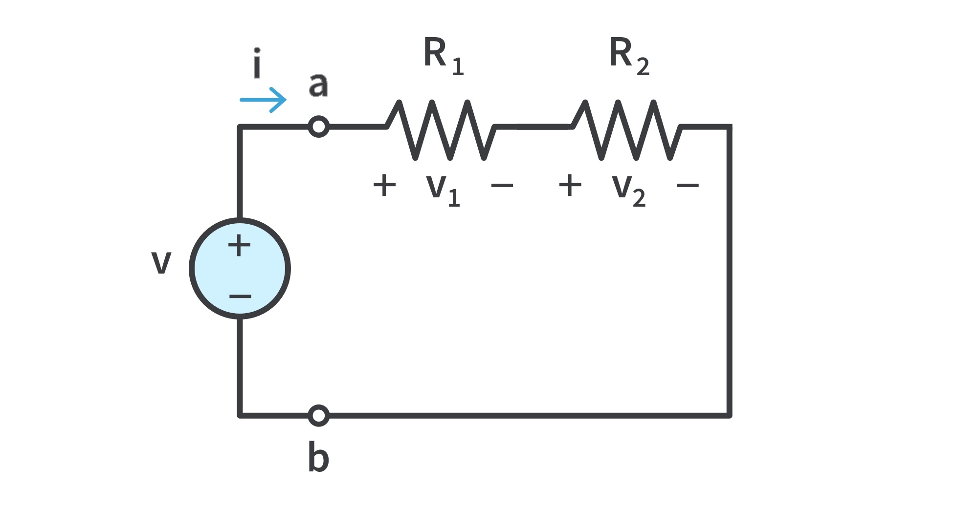
The sign on each voltage is the polarity of the terminal encountered first as we travel around the loop. Consider the circuit:
Suppose we go around the loop clockwise as shown; voltages would be -v1, +v2, +v3, -v4, and v5. Thus, KVL yields
or
If we had traveled counterclockwise, the signs are reversed and the equations remain the same.
Alternative interpretation of KVL: Sum of voltage drops = Sum of voltage rises
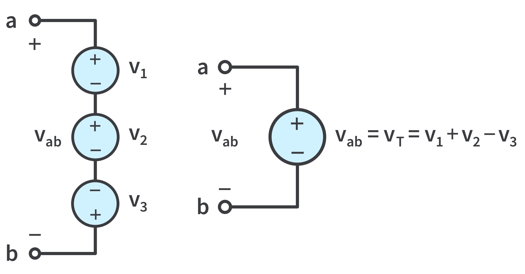
KVL can be applied to voltage sources in series: the combined voltage is the algebraic sum of the individual voltages.
Voltage sources in series and the equivalent circuit
To avoid violating KVL, a circuit cannot contain two different voltage sources v1 and v2 in parallel unless v1 = v2 .
Series Resistors and Voltage Division
Principle of voltage division: the source voltage v is divided among the resistors (in series) in direct proportion to their resistances; the larger the resistance, the larger the voltage drop.
Resistors connected in series have the same current passing through them.
In general, if a voltage divider has N resistors
in series with the source voltage v, the nth resistor will have a voltage drop of
Consider the (voltage divider) circuit
Recall: for N resistors in series the equivalent resistance is
To determine the voltage across each resistor in a 2-resistor circuit,
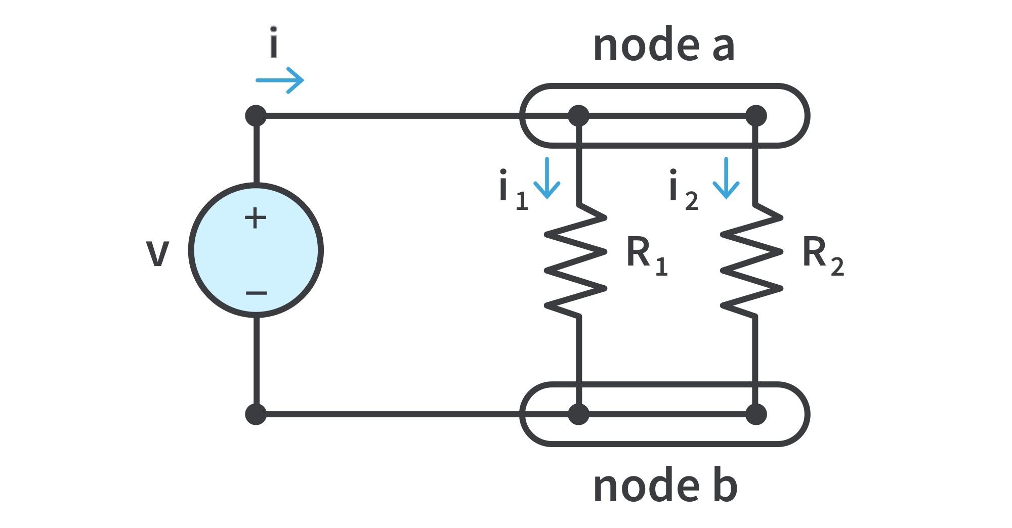
Parallel Resistors and Current Division
Principle of current division: the total current i is shared by the resistors (in parallel) in inverse proportion to their resistances; the larger current flows through the smaller resistance.
Resistors connected in parallel have the same voltage across them.
Consider the (current divider) circuit:
Recall: for 2 resistors in parallel, the equivalent resistance is
To determine the current through each resistor in the circuit given the total current i entering node a,
It must be emphasized that this applies only to two resistors in parallel.
Recall: for a circuit with N resistors in parallel the equivalent resistance is
Wye-Delta Transformations
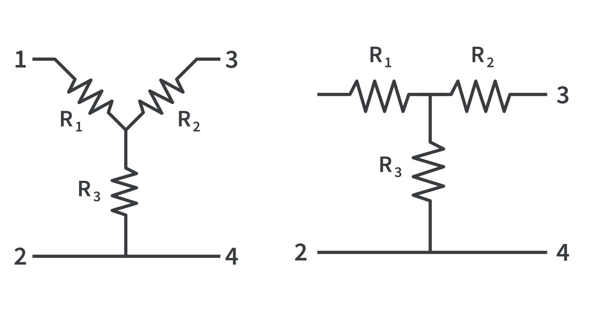
Circuits can be simplified by using three-terminal equivalent networks. These are the wye (Y) or tee (T) network and the delta (Δ) or pi (Π) network shown.
Wye (Y) or Tee (T) networkDelta or Pi network
These networks occur by themselves or as part of a larger network. They are used in three-phase networks, electrical filters, and matching networks.
Wye-Delta Transformations
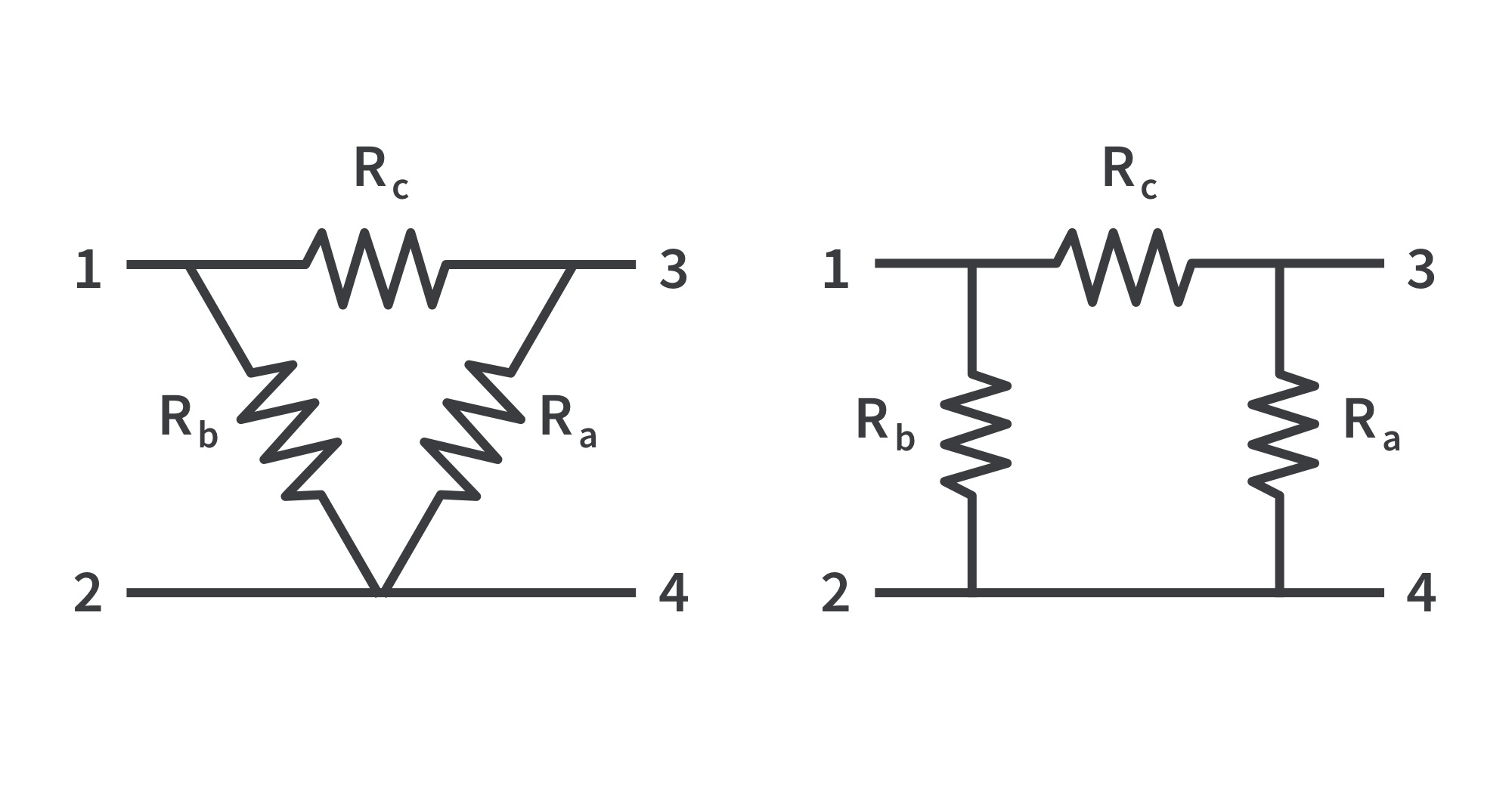
Delta to Wye Conversion
Suppose it is more convenient to work with a Y network instead of a Δ configuration. We superimpose a wye network on the existing Δ network and find the equivalent resistances in the Y network.
To obtain the equivalent resistances in the wye network, the resistance between each pair of nodes in the Δ (or Π) network should be the same as the resistance between the same pair in the Y (or T) network.
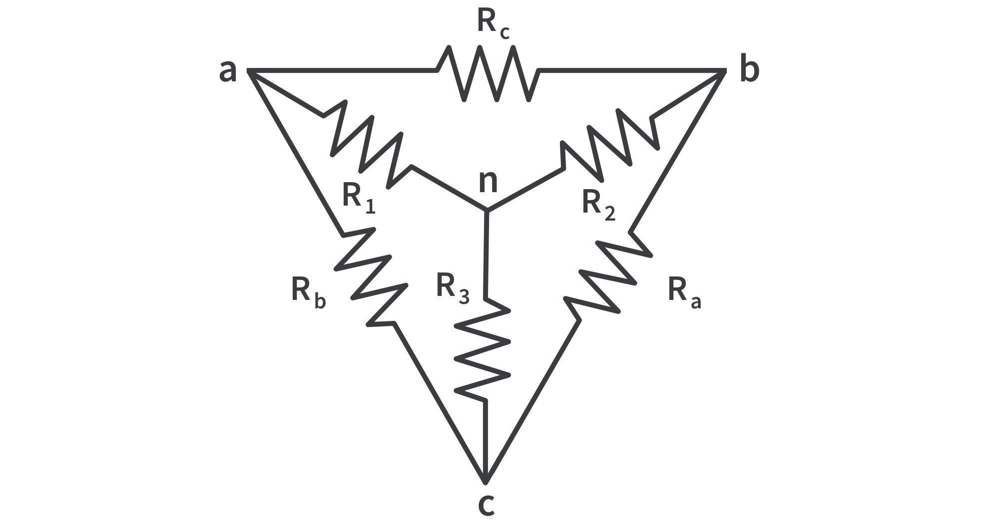
To transform a ∆ network to Y, we create an extra node n as shown
Conversion rule: Each resistor in the Y network is the product of the resistors in the two adjacent Δ branches, divided by the sum of the three Δ resistors.
Following this rule, the resistances can be obtained
Wye-Delta Transformations
Wye to Delta Conversion
The conversion rule for Y to Δ:Each resistor in the Δ network is the sum of all possible products of Y resistors taken two at a time, divided by the opposite Y resistor.
Following this rule, the resistances can be obtained
The Y and Δ networks are said to be balanced when
Under these conditions, conversion formulas become
or
Get the latest tools and tutorials, fresh from the toaster.


 .
.  is the number of branches connected to the node,
  is the nth current entering (or leaving) the node.

 .
.  is the number of voltages in the loop (or branches in the loop),
  is the mth voltage.