Circuit analysis using node voltages as the circuit variables
Convenient and reduces the number of equations one must solve simultaneously
Given a circuit with n nodes without voltage sources, the nodal analysis of the circuit involves taking the following three steps.
First, select a node as the reference node. Assign voltages v1, v2, ..., vn-1 to the remaining nodes. The voltages are referenced with respect to the reference node.
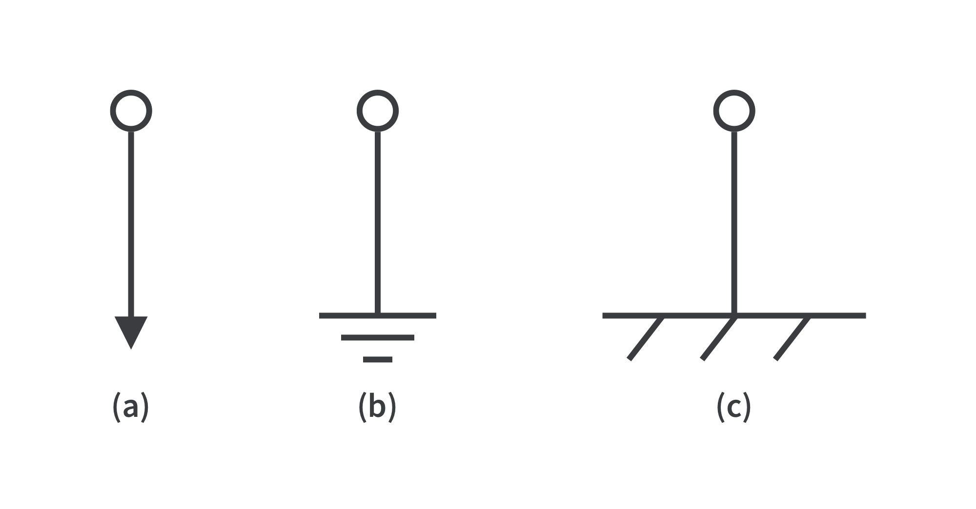
The reference node is commonly called the ground since it is assumed to have zero potential. A reference node is indicated by any of the three symbols:
When the potential of the earth is used as reference, we use the earth ground (a) or (b).
Define node voltages with respect to the reference node. Consider the circuit below. Node 0 is the reference node (), while nodes 1 and 2 are assigned voltages and , respectively. Each node voltage is the voltage rise from the reference node to the corresponding non-reference node; simply the voltage of that node with respect to the reference node.
Second, apply KCL to each of the n - 1 non-reference nodes. Use Ohm’s law to express the branch currents in terms of node voltages.
The circuit is redrawn, where currents and are the currents through resistors and , respectively.
Applying KCL, node 1:
node 2:
Resistance is a passive element; by the passive sign convention, current flows from a higher potential to a lower potential in a resistor. Expressed in Ohm’s law,
Combining the equations, I1 and I2 are:
Finally, solve the resulting simultaneous equations to obtain the unknown node voltages. Any standard method can be used: substitution, elimination, Cramer’s rule, or matrix inversion.
Nodal Analysis with Voltage Sources
Case 1: If a voltage source is connected between the reference node and a non-reference node, set the voltage at the non-reference node equal to the voltage of the voltage source. In the circuit below, for example,
Analysis is somewhat simplified by this knowledge of the voltage at this node.
Case 2: If the voltage source (dependent/independent) is connected between two non-reference nodes, the two nonreference nodes form a generalized node or supernode; apply both KCL and KVL to determine the node voltages.
A supernode is formed by enclosing a (dependent/independent) voltage source connected between two nonreference nodes and any elements connected in parallel with it. A supernode can be formed by more than two nodes.
Properties of a supernode:
The voltage source inside the supernode provides a constraint equation needed to solve for the node voltages.
A supernode has no voltage of its own.
A supernode requires the application of both KCL and KVL.
Analyze the circuit using the same three steps mentioned in the previous section except that now we have supernodes. KCL must be satisfied at a supernode like any other node. At the supernode,
or
To apply KVL to the supernode, we redraw the circuit as shown below
Going around the loop in the clockwise direction gives
From the previous equations and the fact that
we obtain the node voltages.
Mesh Analysis
Uses mesh currents as the circuit variables; applies KVL to find unknown currents
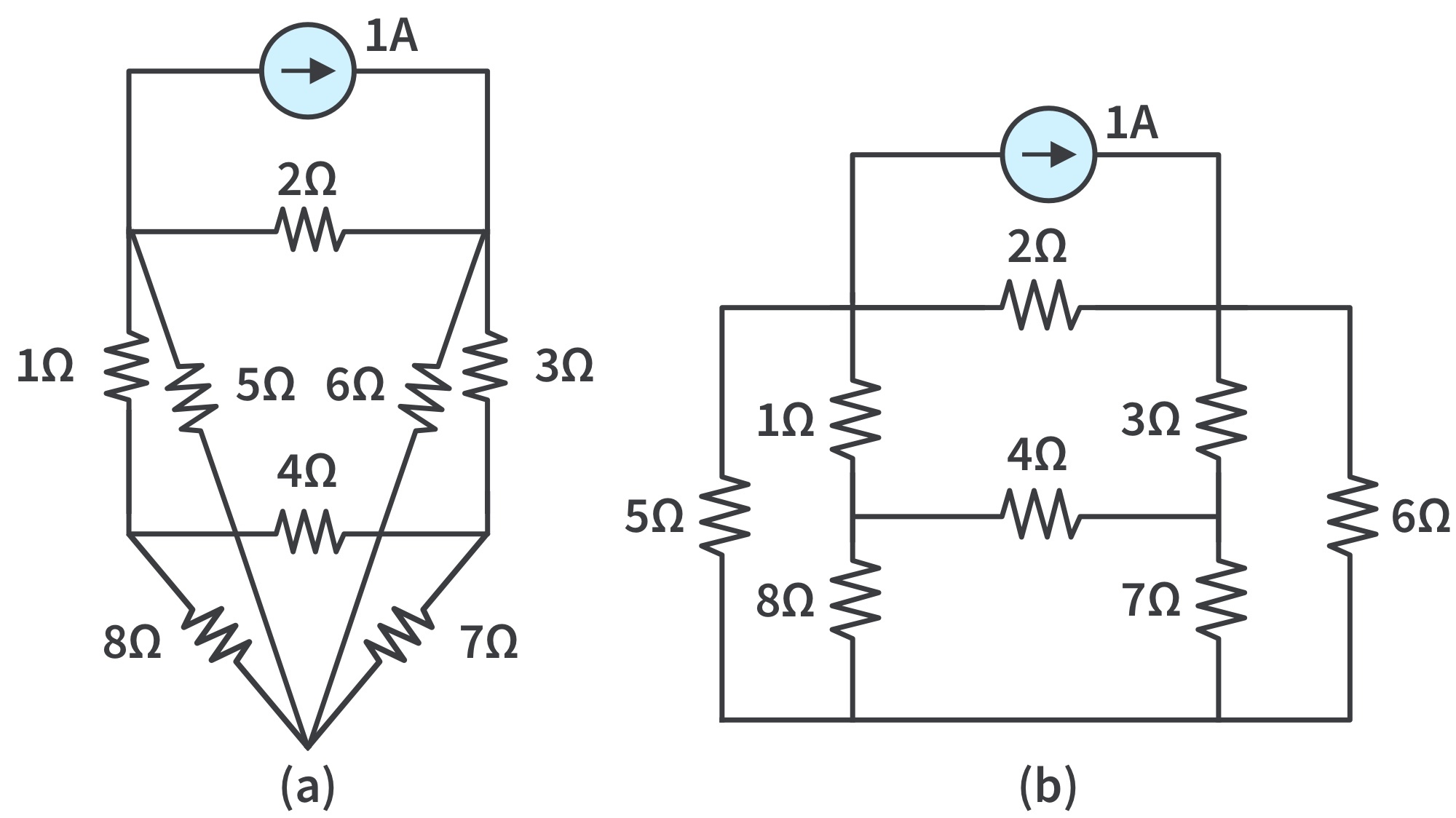
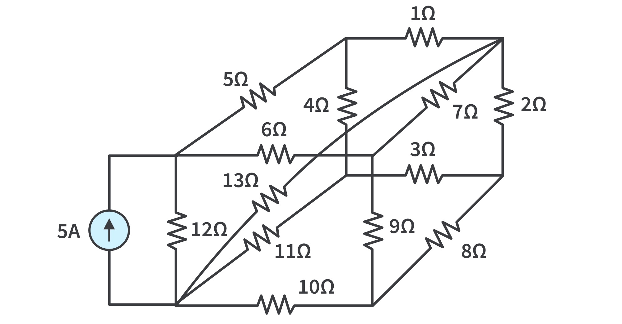
Only applicable to a circuit that is planar; one that can be drawn in a plane with no branches crossing one another; otherwise it is nonplanar. A circuit may have crossing branches and still be planar if it can be redrawn such that it has no crossing branches.
The circuit (a) has two crossing branches, but it can be redrawn as (b); hence, it is planarA nonplanar circuit
Recall that a loop is a closed path with no node passed more than once.
A mesh is a loop that does not contain any other loop within it.
The current through a mesh is known as mesh current.
In this section, we will apply mesh analysis to planar circuits that do not contain current sources.
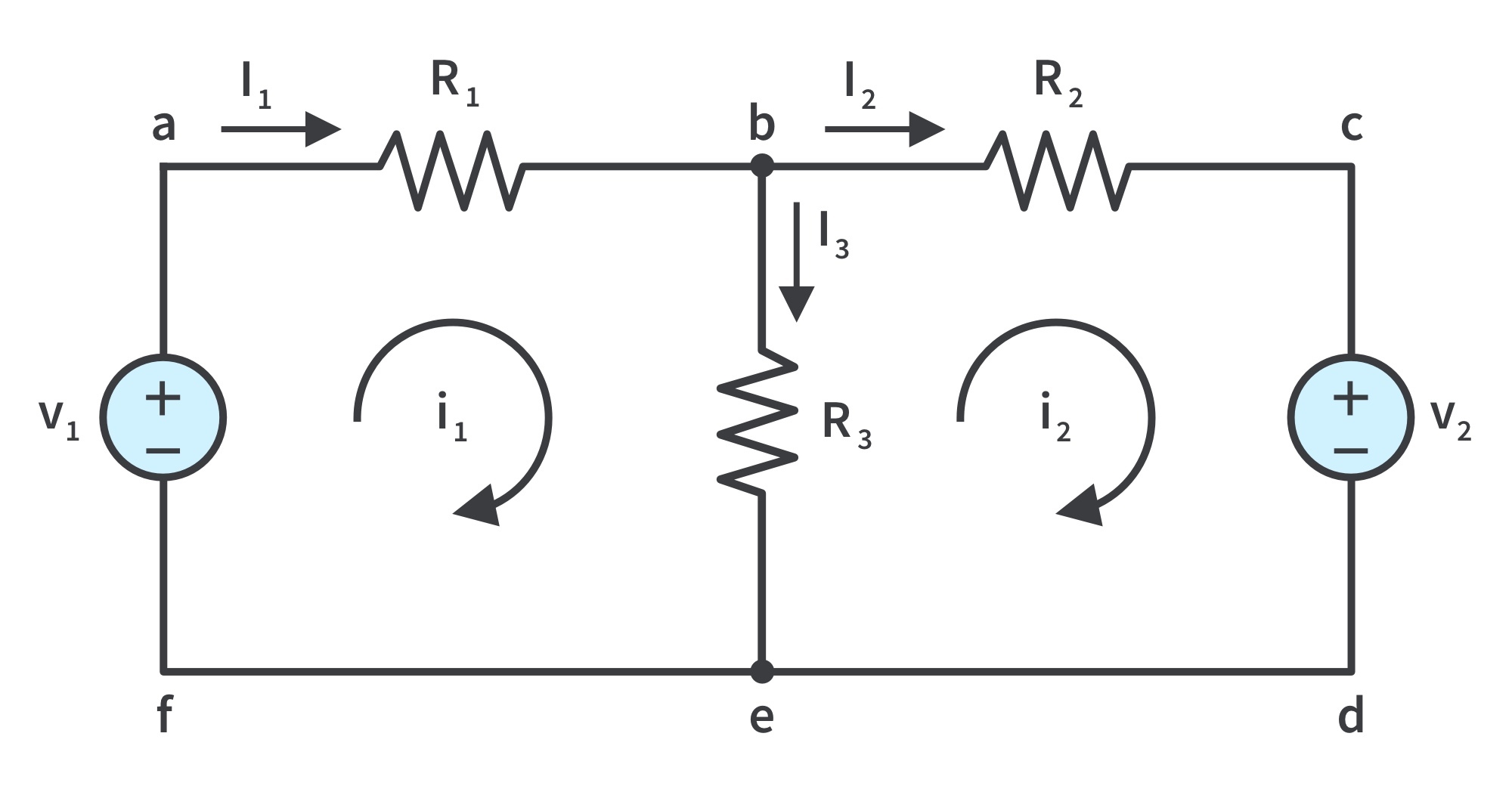
Consider the circuit with 2 meshes:
Paths abefa and bcdeb are meshes, but path abcdefa is not a mesh
In the mesh analysis of a circuit with n meshes, we take the following three steps:
Step 1: Assign mesh currents to the meshes.
This step requires that in the circuit above, mesh currents and are assigned to meshes 1 and 2. It is conventional to assume that each mesh current flows clockwise.
Step 2: Apply KVL to each of the n meshes. Use Ohm’s law to express the voltages in terms of the mesh currents.
Applying KVL to mesh 1, or
Applying KVL to mesh 2, or
Step 3: Solve the resulting simultaneous equations to get the mesh currents.
Any technique can be used to solve the simultaneous equations.
Recall: if a circuit has nodes, branches, and independent loops or meshes, then . Hence, independent simultaneous equations are required to solve the circuit using mesh analysis.
Notice that the branch currents are different from the mesh currents unless the mesh is isolated. To distinguish between the two types of currents, we use for a mesh current and for a branch current.
The current elements are algebraic sums of the mesh currents. It is evident from the circuit that .
Mesh Analysis with Current Sources
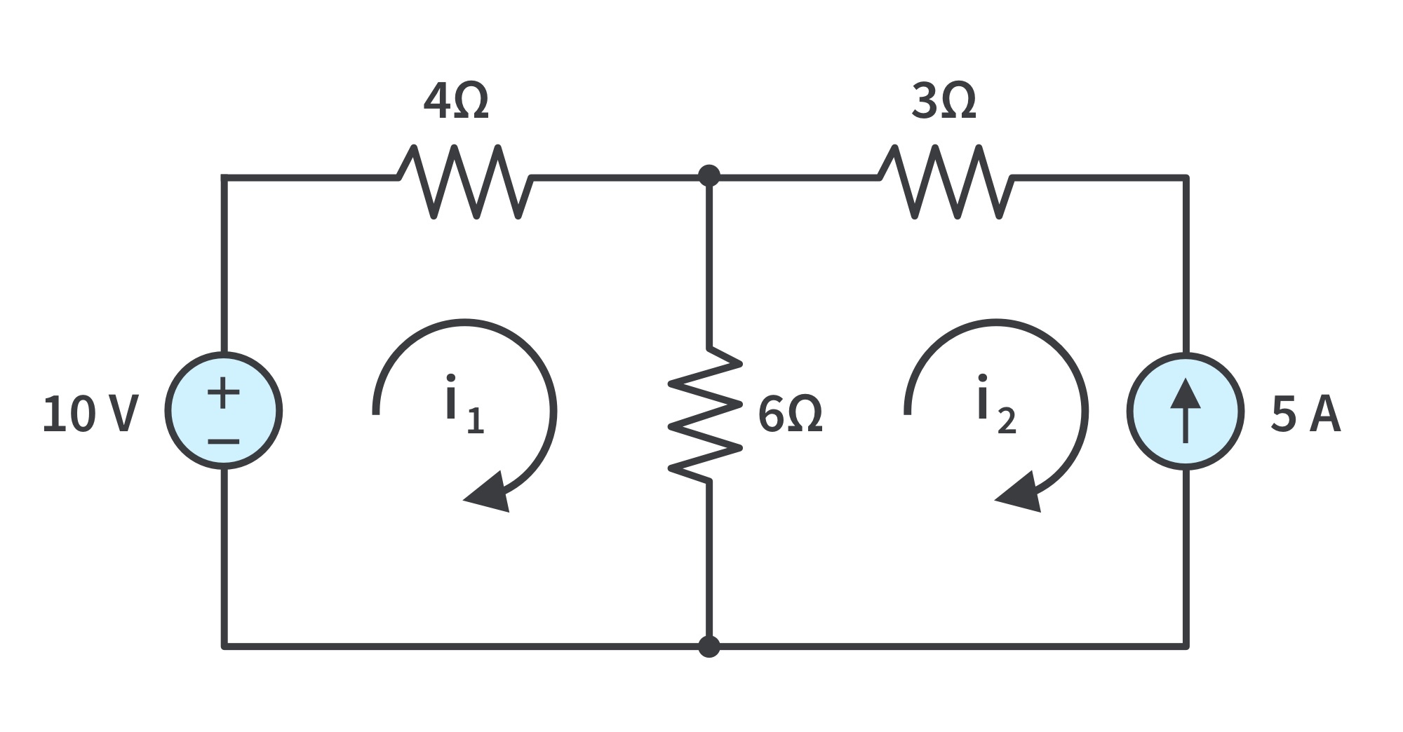
Case 1: When a current source exists only in one mesh:
Consider the circuit in below, for example. We set and write a mesh equation for the other mesh in the usual way; that is,
Case 2: When a current source exists between two meshes:
A supermesh results when two meshes have a (dependent or independent) current source in common.
Properties of a supermesh:
The current source in the supermesh provides the constraint equation necessary to solve for the mesh currents.
A supermesh has no current of its own.
A supermesh requires the application of both KVL and KCL.
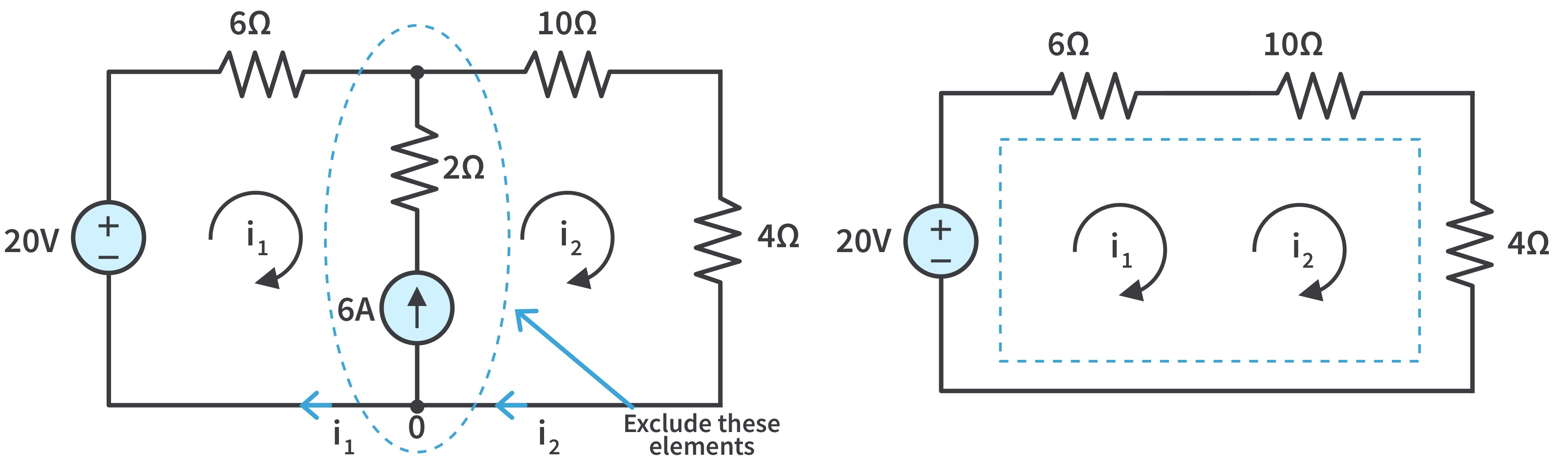
Consider the circuits below, for example. We create a supermesh by excluding the current source and any elements connected in series with it.
(a) Two meshes having a current source in common, (b) a supermesh, created by excluding the current source.
As shown, we create a supermesh as the periphery of the two meshes and treat it differently. If a circuit has two or more supermeshes that intersect, they should be combined to form a larger supermesh.
Why treat the supermesh differently? Because mesh analysis applies KVL— which requires that we know the voltage across each branch—and we do not know the voltage across a current source in advance.
However, a supermesh must satisfy KVL like any other mesh. Applying KVL to the supermesh in (b),
We apply KCL to a node in the branch where the two meshes intersect. Applying KCL to node 0 (a) gives
Solving the two equations, we get
Get the latest tools and tutorials, fresh from the toaster.


 ), while nodes 1 and 2 are assigned voltages
  and
and  , respectively.
 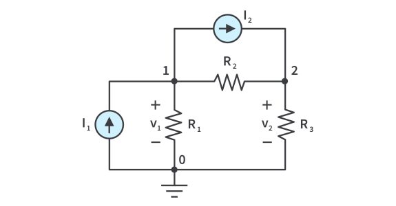 Each node voltage is the voltage rise from the reference node to the corresponding non-reference node; simply the voltage of that node with respect to the reference node.
 and
and  are the currents through resistors
  and
and  , respectively.
 to the
  meshes.
 and
and  are assigned to meshes 1 and 2. It is conventional to assume that each mesh current flows clockwise.
 or
or 
 or
or 
 simultaneous equations to get the mesh currents.
 nodes,
  branches, and
  independent loops or meshes, then
  . Hence,
  for a mesh current and
  for a branch current.
 are algebraic sums of the mesh currents. It is evident from the circuit that
  .
. We set
  and write a mesh equation for the other mesh in the usual way; that is,


