A second-order circuit is characterized by a second-order differential equation. It consists of resistors and the equivalent of two energy storage elements
Finding Initial and Final Values
First, focus on the variables that cannot change abruptly; capacitor voltage and inductor current.
There are two key points to keep in mind in determining the initial conditions.
Carefully handle the polarity of voltage across the capacitor and the direction of the current through the inductor; and are defined strictly according to the passive sign convention.
The capacitor voltage is always continuous so that and the inductor current is always continuous so that , where denotes the time just before switching and is the time just after, assuming that the switching takes place at .
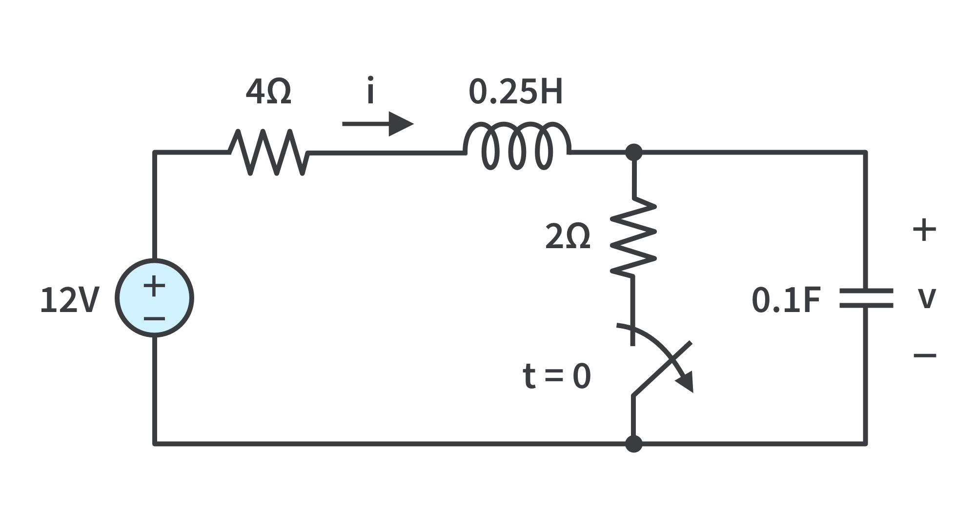
Example: The switch in Fig. 1 has been closed for a long time. It is open at t=0. We are going to find:
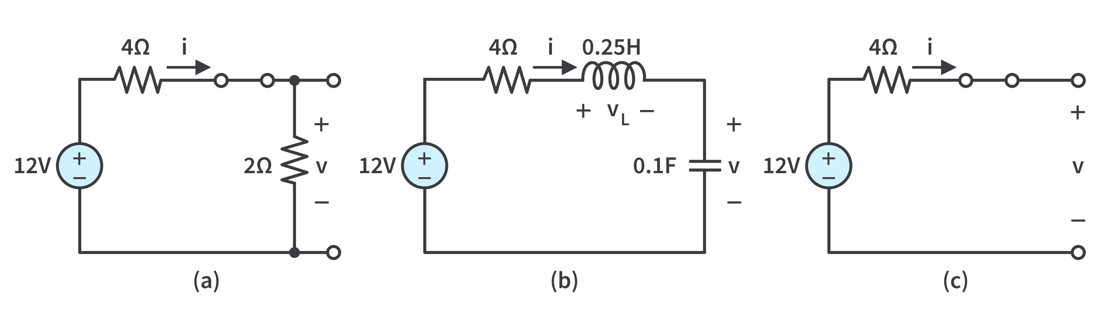
Fig 1: Example circuitFigure 2: Equivalent circuit of that in Fig.1 for: (a) t=0-, (b) t=0+, (c) t->infinity
a. The switch closed a long time before t = 0 means that the circuit is at dc steady-state at t = 0. Thus, the inductor acts like a short circuit, while the capacitor acts like an open circuit. At t = 0-,
b. At t = 0+, the switch is open and the same current flows through both the inductor and capacitor. Hence, ic(0+) = i(0+) = 2A
Since ic = C(dv/dt), dv/dt = ic/c and
Similarly, since
We now obtain VL by applying KVL to the loop in Fig. 2(b). The result is
Thus,
c. For t > 0, the circuit undergoes transience. But as t -> ∞, the circuit reaches steady-state again. The inductor acts like a short circuit and the capacitor like an open circuit. Thus, we have
The Source-Free Series RLC Circuit
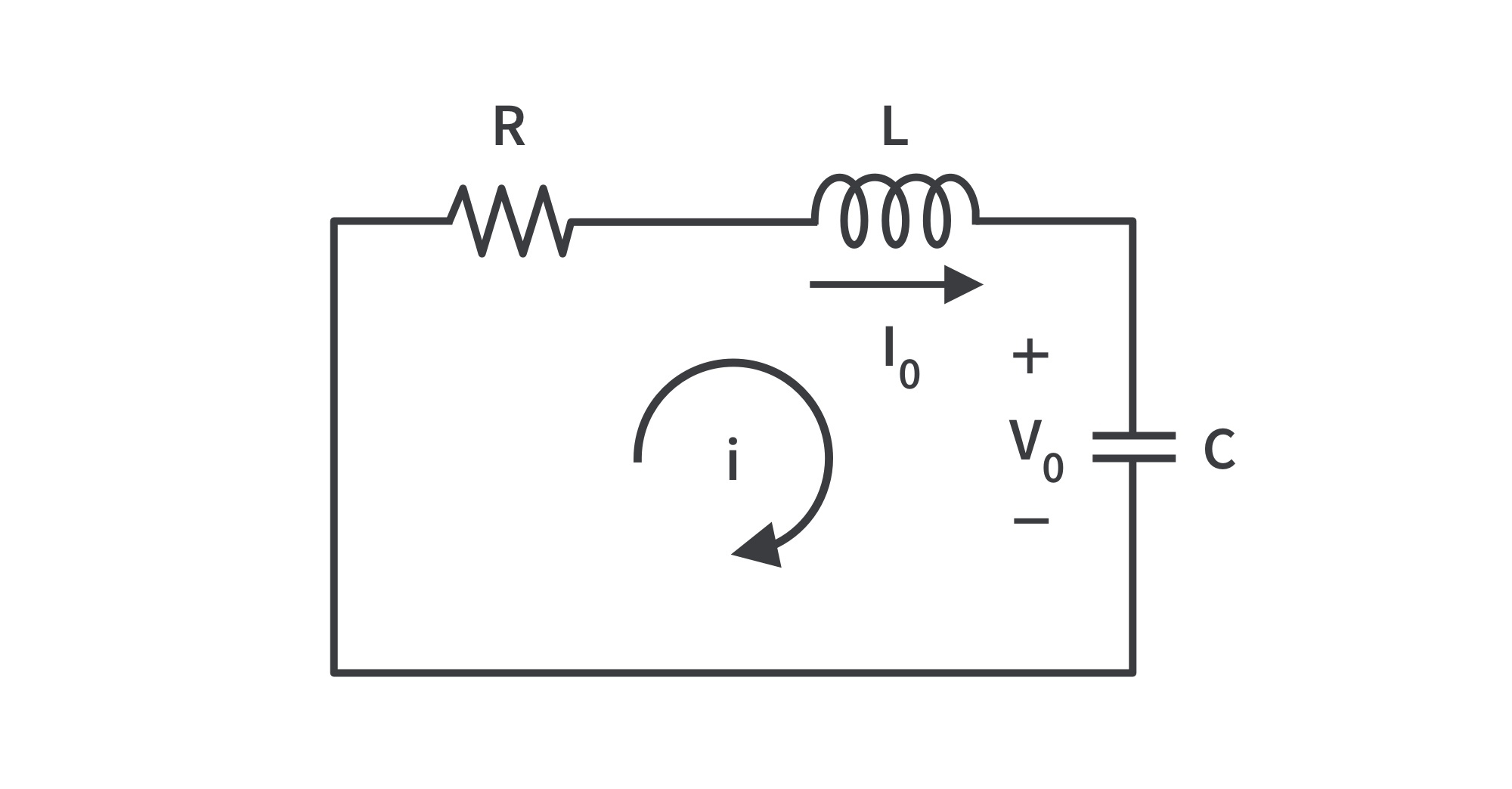
A series RLC circuit is shown in Fig. 3. The circuit is being excited by the energy initially stored in the capacitor and inductor.
Figure 3: A source-free series RLC circuit
The energy is represented by the initial capacitor voltage and initial inductor current . Thus, at t=0, .
Applying KVL around the loop and differentiating with respect to t,
This is a second-order differential equation. The solution is of the form and substituting this to the DE, the characteristic equation is
where
are the two roots of the characteristic equation of the differential. A more compact way of expressing the roots is
where
The roots and are called natural frequencies, measured in nepers per second (Np/s).
is known as the resonant frequency or strictly as the undamped natural frequency, expressed in radians per second (rad/s).
is the neper frequency expressed in Np/s.
Since there are two possible solutions from the two values of ,
A complete or total solution would therefore require a linear combination of and . Thus the natural response of the series RLC circuit is , where the constants and are determined from initial values.
There are three types of solutions:
If > , the overdamped case; roots are unequal and real.
If = , the critically damped case; roots are equal and real.
If < , the underdamped case; roots are complex.
Overdamped Case (> )
implies > . When this happens, both roots and are negative and real. The response is , which decays and approaches zero as t increases. Fig. 4 illustrates a typical overdamped response.
Figure 4: Overdamped response, i(0)=0
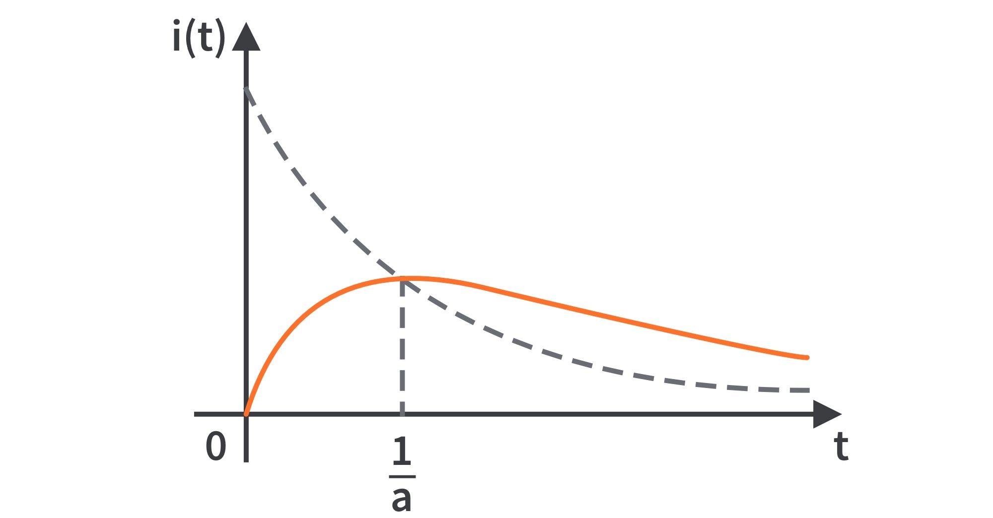
Critically Damped Case ( = )
When = , = and . The second-order differential equation becomes
Solving the DE gives the natural response of the critically damped circuit: a sum of a negative exponential and a negative exponential multiplied by a linear term, .
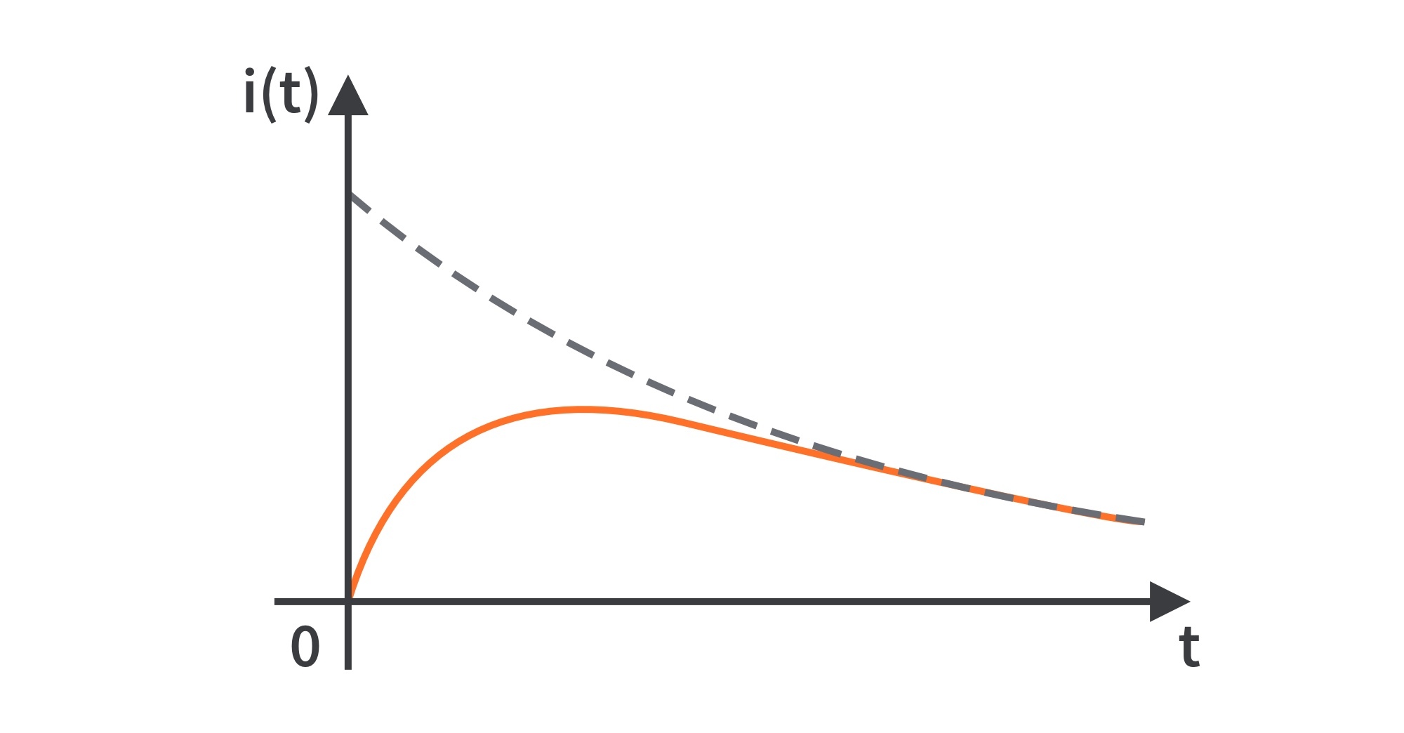
A typical critically damped response is shown in Fig. 5. It is a sketch of , which reaches a maximum value of at , one time constant, and then decays all the way to zero.
Figure 5: Critically damped response, i(0)=0
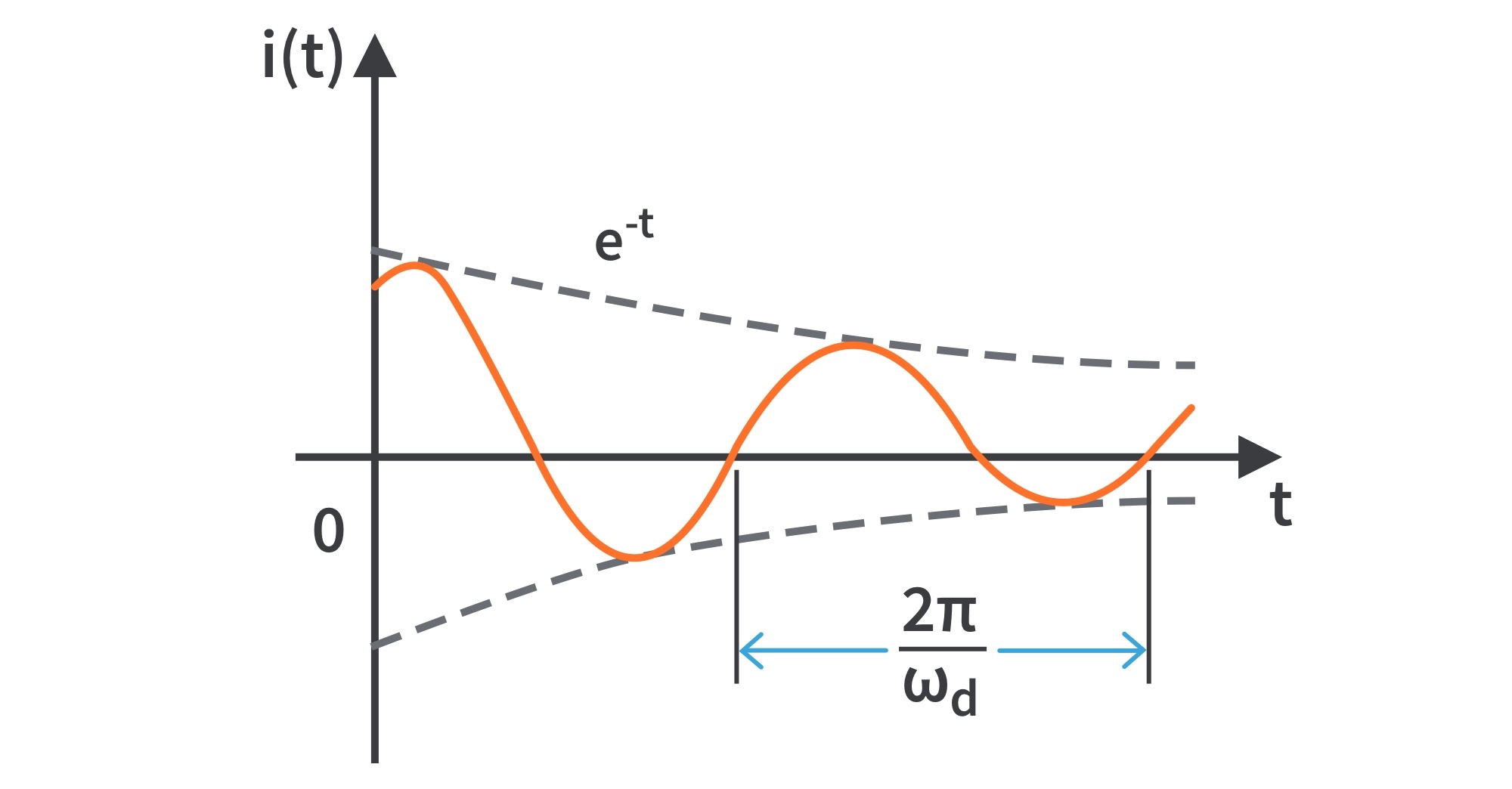
Underdamped Case ( < )
When < , < . The roots may be written as , where and which is called the damped frequency.
Both and are natural frequencies because they help determine the natural response.
Using Euler's identities, and replacing constants with constants , the natural response is .
The natural response for this case is exponentially damped and oscillatory in nature. It has a time constant of and a period of . Fig. 6 shows a typical underdamped response.
Figure 6: Underdamped response
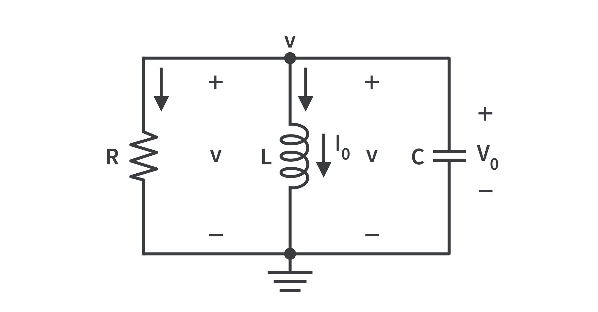
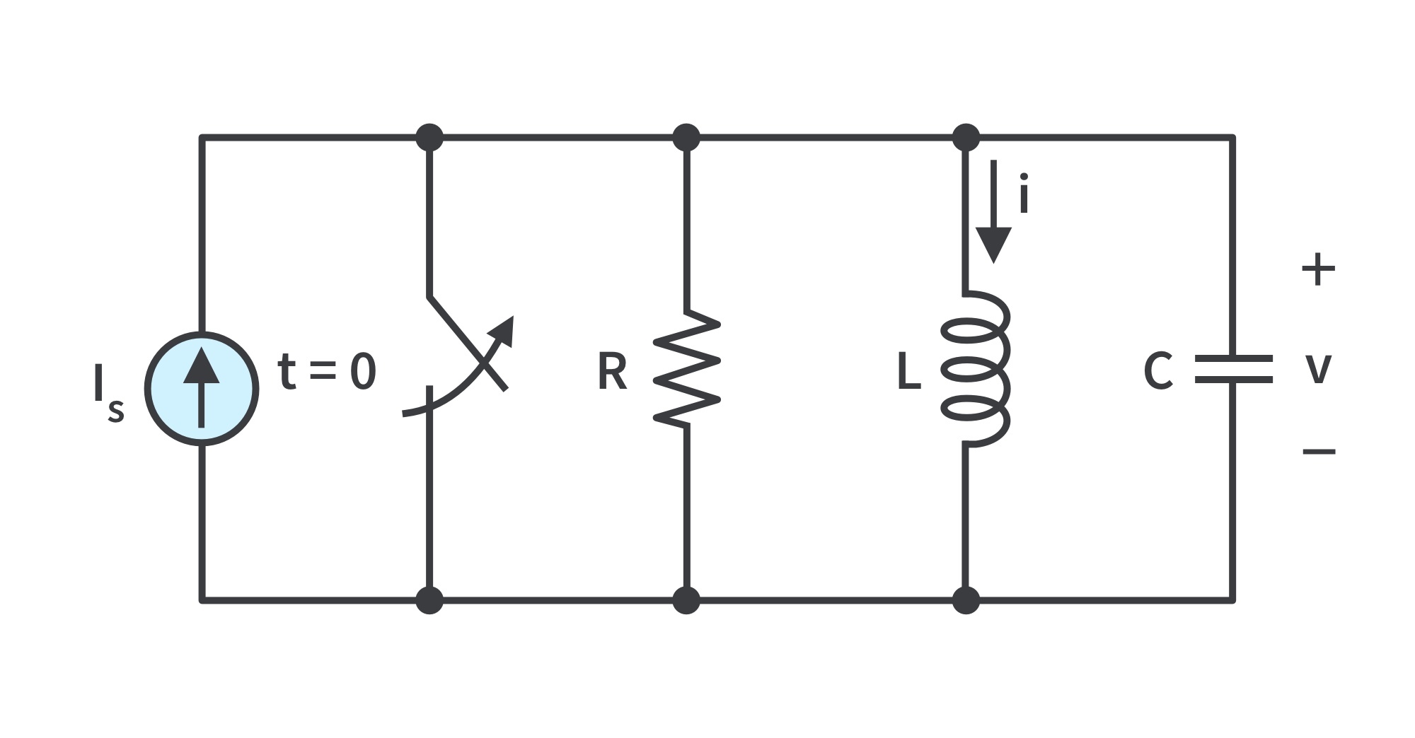
The Source-Free Parallel RLC Circuit
Consider the parallel RLC circuit shown in Fig. 7. Assume initial inductor current and initial capacitor voltage , and .
Figure 7: A source-free parallel RLC circuit
The three elements in parallel have the same voltage across. According to the passive sign convention, the current through each element is leaving the top node. Applying KCL at the top node, taking the derivative with respect to t and dividing by C results in
The characteristic equation is obtained as
The roots of the characteristic equation are
Again, there are three possible solutions, depending on whether > , = , or <
Overdamped Case
> when > , the roots of the characteristic equation are real and negative. The response is
Critically Damped Case
For = , , the roots are real and equal so that the response is
Underdamped Case
When < , < . In this case the roots are complex and may be expressed as .
The response is
The constants in each case can be determined from the initial conditions: and . To find ,
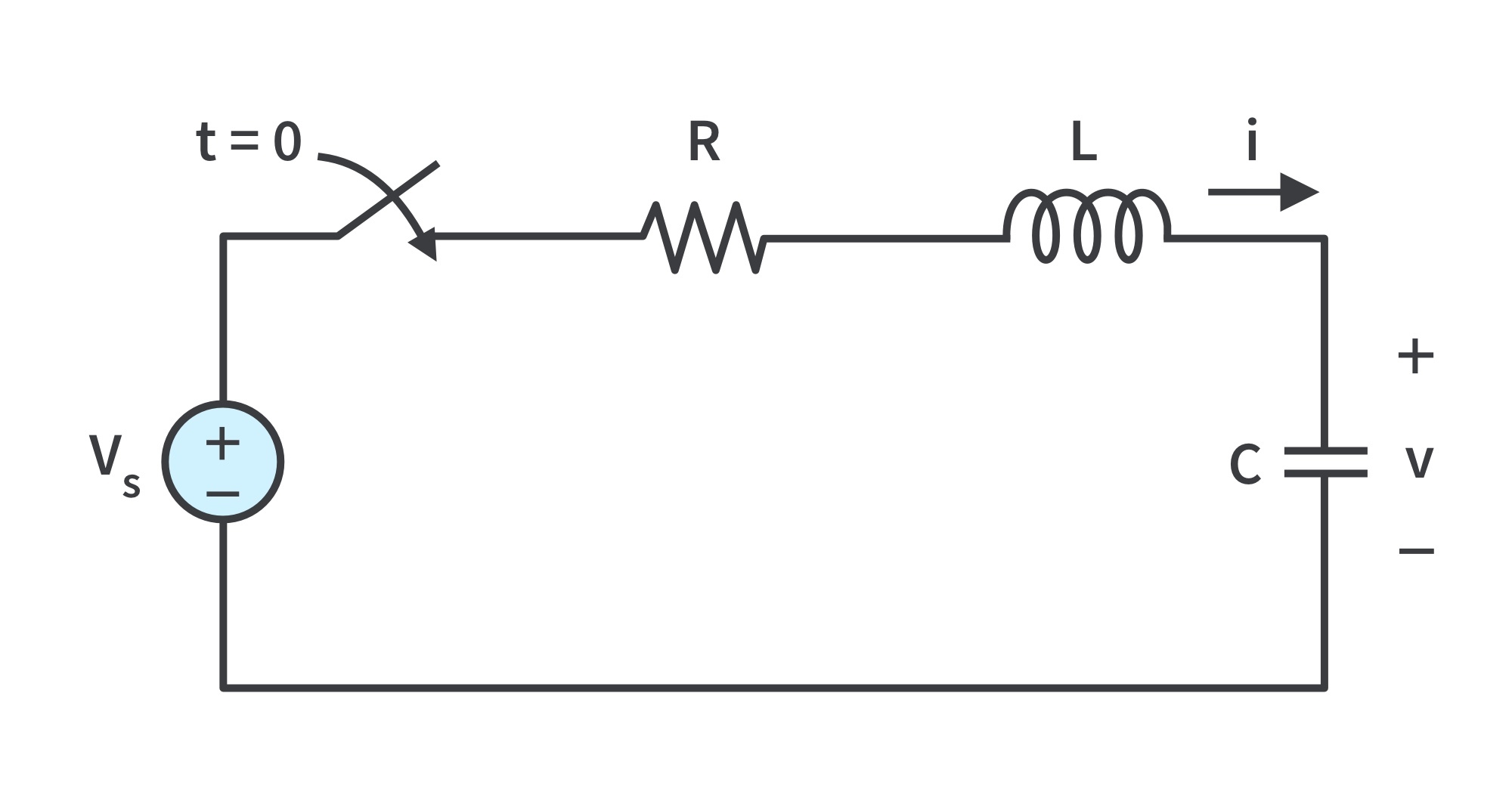
Step Response of a Series RLC Circuit
Consider the series RLC circuit shown in Fig. 8.
Figure 8: Step voltage applied to a series RLC circuit
Applying KVL around the loop for t>0,
Substituting i = C dv/dt,
The solution has two components: the transient response (vt(t)) and the steady-state response (vss(t)) ; that is,
vt(t) for each case:
Overdamped:
Critically damped:
Underdamped:
In the circuit in Fig. 8, the final value of the capacitor voltage is the same as the source voltage VS. Hence the steady-state response is
Complete solutions for the three cases:
Overdamped:
Critically damped:
Underdamped:
and are, respectively, the voltage across C and the current through L.
are obtained from the initial conditions: .
Once the capacitor voltage is known, can be obtained which is the same current through C, L, and R.
Hence, the voltage across the resistor is , while the inductor voltage is
Step Response of a Parallel RLC Circuit
Consider the parallel RLC circuit shown in Fig. 9.
Figure 9: Parallel RLC circuit with an applied current
Applying KCL at the top node for t>0,
Substituting v = L di/dt and dividing by LC,
Again, the complete solution consists of the transient response (it(t)) and the steady-state response (iss(t)) ; that is,
it(t) for each case
Overdamped:
Critically damped:
Underdamped:
The steady-state response is the final value of . In the circuit, the final value of the current through L is the same as the source current .
Complete solutions for the three cases
Overdamped:
Critically damped:
Underdamped:
These equations only apply for finding the inductor current .
are obtained from the initial conditions for .
Once the inductor current is known, can be obtained which is the same voltage across C, L, and R.
Hence, the current through the resistor is , while the capacitor current is .
Get the latest tools and tutorials, fresh from the toaster.


 across the capacitor and the direction of the current
  through the inductor;
  and
and  are defined strictly according to the passive sign convention.
 and the inductor current is always continuous so that
  , where
  denotes the time just before switching and
  is the time just after, assuming that the switching takes place at
  .
. and initial inductor current
  . Thus, at t=0,
  .
. and substituting this to the DE, the characteristic equation is
 and
and  are called natural frequencies, measured in nepers per second (Np/s).
 is known as the resonant frequency or strictly as the undamped natural frequency, expressed in radians per second (rad/s).
 is the neper frequency expressed in Np/s.
 ,
, 
 and
and  . Thus the natural response of the series RLC circuit is
  , where the constants
  and
and  are determined from initial values.
 >
>  , the overdamped case; roots are unequal and real.
 >
>  )
)
 implies
  >
>  . When this happens, both roots
  and
and  are negative and real. The response is
  , which decays and approaches zero as t increases. Fig. 4 illustrates a typical overdamped response.
 and
and  . The second-order differential equation becomes
 .
. , which reaches a maximum value of
  at
at  , one time constant, and then decays all the way to zero.
 , where
  and
and  which is called the damped frequency.
 and
and  are natural frequencies because they help determine the natural response.
 and replacing constants
  with constants
  , the natural response is
  .
. and a period of
  . Fig. 6 shows a typical underdamped response.
 and initial capacitor voltage
  ,
, and
and  .
. ,
,  >
>  , the roots of the characteristic equation are real and negative. The response is
 , the roots are real and equal so that the response is
  <
<  . In this case the roots are complex and may be expressed as
  .
. in each case can be determined from the initial conditions:
  and
and  . To find
  ,
,


 and
and  are, respectively, the voltage across C and the current through L.
 are obtained from the initial conditions:
  .
. is known,
  can be obtained which is the same current through C, L, and R.
 , while the inductor voltage is


 . In the circuit, the final value of the current through L is the same as the source current
  .
.


 .
. are obtained from the initial conditions for
  .
. is known,
  can be obtained which is the same voltage across C, L, and R.
 , while the capacitor current is
  .
.


